Project Operations
A project encompasses all 3D data obtained by scanning and postprocessing that can be saved to disk and accessed for later use. In addition, it contains command history and measurement results. For each project, a corresponding folder contains all project data as well as a project file describing the structure of that data.
Artec Studio can display project statistics. It includes information on number of scans, surfaces (frames), polygons, vertices and UV coordinates.
To access this data, call a right-click menu for any Workspace object and select Project info.
If you want to collate data on the selected scans with the total numbers for the project, first mark the required scans using with the  flag.
flag.
Creating a Project
To start a new project, select the File → New project menu option. It is a best practice to save this project to a specific folder before you start scanning. If you start scanning with the Save scans directly to disk option enabled or import scans from Ray, a temporary project is created in the Windows temporary folder or another directory if you specified one in Settings.
Saving a Project
You can save your project using the File → Save project menu option, by clicking  at the top of the Workspace panel or by hitting Ctrl + S.
For projects that allocate more than 6 GB of memory, the dialog [1] will prompt you to compress project data using the maximum settings (see Data-Compression Level). To save project to a file compatible with all Artec Studio versions using medium compression settings, click Skip. You can reconvert the project with the maximum compression to ensure full compatibility with the previous version of software. To this end, move the slider to the middle or the left position and save the project again.
at the top of the Workspace panel or by hitting Ctrl + S.
For projects that allocate more than 6 GB of memory, the dialog [1] will prompt you to compress project data using the maximum settings (see Data-Compression Level). To save project to a file compatible with all Artec Studio versions using medium compression settings, click Skip. You can reconvert the project with the maximum compression to ensure full compatibility with the previous version of software. To this end, move the slider to the middle or the left position and save the project again.
| [1] | You can also disable this dialog: select the corresponding checkbox either in the message or in the Pefromance tab of the application’s Settings. |
While you’re working with a saved project, the header of Workspace panel displays its name and the application window its full path. Save project from time to time in the course of processing or otherwise using the scanned material.
Note
Artec Studio saves data incrementally, meaning that if you save an existing project, the application will only save newly changed or added data.
Opening Project and Scans
To open an existing project, use the File → Open project menu option, click  at the top of the Workspace panel or hit Ctrl + O.
Note
Files from Artec Studio versions 8, 9, 10 and 11 are mutually compatible. Earlier versions, however, may be unable to open projects saved in a later version using the SPROJ format.
By default, when you open a project, the application will restore it to the state in which it was last saved (the three scan-loading states include loaded, unloaded and key frames only—see Selectively Loading Project Data). To load faster by opening the project without loading any scans, use the Open project (scans not loaded) dropdown menu option under the button. Alternatively, use the same option from the File menu or hit Ctrl + Shift + O.
Note
When Artec Studio opens a project, it will determine the amount of available memory. If the scan you are trying to load requires more memory than is available in your system, the application will process it as an “unloaded” scan.
Opening a Project from Leo
You can obtain projects from Leo via direct connection to the scanner or using an SD card installed in the device.
Connecting to Leo
- Ensure that your Leo scanner and your computer are connected to the same network and you authenticated using the same credentials
- Click File → Import → Leo project (connect to scanner)
- Select the required device from the list and click Connect [2]
- Then using either LKM or ↑ and ↓ select the project that you want to load (Figure 62)
- Click Import. Wait for scans and real-time fusion models (RTF) to appear in the Workspace panel. If the scans contain information on supporting surface and the corresponding option is enabled in Settings, application will also launch base removal.
| [2] | If Artec Studio doesn’t list your Leo, try connecting to the device by manually specifying the IP address. Click Connect by IP to this end. |
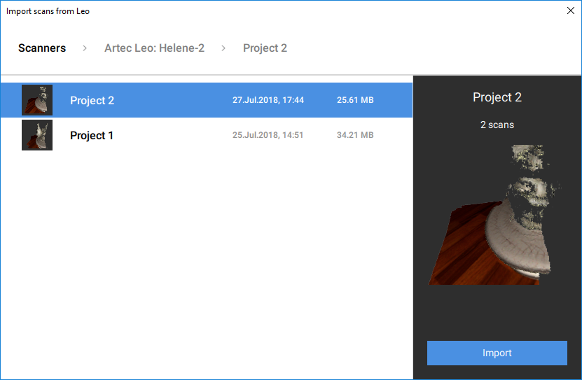
Figure 62 Dialog for selecting Leo projects to import.
Using SD Card
If you want to open Leo scans without having to connect to the device, use the following method:
- On Leo, first copy a project to SD card.
- Then insert the card into the computer with installed Artec Studio.
- Click File → Import → Leo project
- Browse for the required project folder
- Select the folder containing Leo project and click Select folder. Import will start.
Importing Models and Scans
Importing is another way to load data into Artec Studio in place of capturing or opening a project. You can import scan files created in earlier versions of the software, individual frames, as well as point cloud data in the following formats:
SCAN |
Artec 3D scan format |
PLY |
Stanford polygon file format |
STL |
Stereolithography file format |
VRML |
VRML file; actual extension is *.wrl |
OBJ |
Wavefront OBJ file format |
PTX |
Disney per-face texture mapping format |
C3D |
Artec Ray original point cloud |
BTX |
Artec Ray point cloud |
To import a file, use the File → Import → Scans, meshes or point clouds menu option, Ctrl + I or the dropdown menu option for the button. Next, select a file for importing. You can also drag and drop a file into the main Artec Studio window, or just double click on it.
Note
The import process runs in the background, so you can continue working with the scans you’ve already loaded. The progress indicator for the import operation will appear at the bottom of the main application window. To abort the operation, click Cancel in the bottom-right corner.
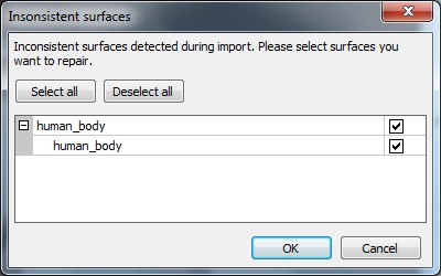
Figure 63 Dialog for selecting surfaces to correct.
Artec Studio will import frame files as individual single-frame scans. After importing each scan, the application calculates the key frames for any scan that contains more than one surface. Also, the application will check the surfaces for defects when the appropriate setting is enabled (see Surface-Consistency Detection During Import). If it finds defects, it will show a dialog with a list of defective surfaces once the import operation is complete. You can then choose which ones should be corrected (see Figure 63).
Exporting Models, Scans and Point Clouds
When you want to store data for future processing, the best approach is to save the project as an SPROJ file or to export the data to the SCAN format. Any Artec Studio version can open the latter format. If you plan to use the data in other applications, however, you should save scans and individual frames in another format.
You may also need to perform one of the following tasks:
| Export one or more scans | File → Export → Scans | Doing so will save all frames to folders with names that match the corresponding scan names. An exception is the SCAN format; in this case, Artec Studio not only stores the frame-by-frame scan structure, but it does so in a single file. |
| Export a single surface | File → Export → Meshes | It works for models. If you, however, marked several scans, models or frames using the button, Artec Studio will suggest merging them. |
| Export Ray scans | File → Export → Point clouds | It works for point-cloud scans from Ray. |
Exporting Scans
To export scans:
- Mark any scans you want to export using the button.
- Select the Export scans… command in the dropdown menu option of in the Workspace panel.
- Click the … button to open and specify the destination folder.
- Select Scan export format using the eponymous dropdown list (see Figure 64).
- If the selected format supports textures, also specify the texture format.
- Select the Apply transformation checkbox, or leave it cleared (for more information, consult Understanding How Artec Studio Applies Transformations).
- Click OK.
Note
The export process for models and scans runs in the background, so the application will allow you to continue working with the scans. The progress indicator for the export operation will appear at the bottom of the main application window. To abort the operation, click Cancel in the bottom-right corner.
Exporting Meshes (Models)
To export a mesh:
Mark one or more models using
or select frames in the scan by clicking on them while holding the Ctrl key.Select the Export meshes… command in the dropdown menu of the
button in the Workspace panel.Tip
File → Export → Meshes command and Ctrl+Shift+E hot key also work.
Specify the destination folder, enter the file name, and select the appropriate mesh format from the dropdown list [3].
Click Save.
If the model has texture and the format supports it, specify the Texture export format in the new dialog (see Storing and Exporting Color Information).
Click Export.
| [3] | If you type an extension in the file name field, application will use it rather than the selected mesh file format. |
See also
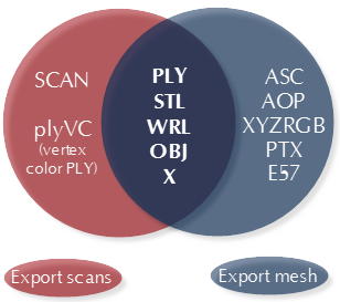
Figure 64 Formats available for each command as well as for both commands.
Exporting Point Clouds
You can export point-cloud scans obtained from Ray scanner to either of the following formats:
PTX |
Leica Geosystems Cyclone Point Cloud. Important! Don’t confuse with Disney Ptex |
XYZ |
XYZRGB file format |
BTX |
Artec Ray point cloud; various versions (v2, v3, v5, v6). |
- Mark one or more point-cloud scans using flag in Workspace. Ensure that you have selected a point-cloud scan by double-clicking its name: the panel must show point-cloud properties.
- Select File → Export → Point clouds.
- Specify the destination folder and required format and click Save.
Understanding How Artec Studio Applies Transformations
Artec Studio offers two options for exporting surfaces:
- Store surfaces using the scanner coordinates and create
XFtext files that contain the coordinates calculated during registration. To use this approach, clear the Apply transformations checkbox. - Store surfaces that are relocated to the positions calculated during registration. In this case,
XFfiles contain no relevant data. To use this approach, select the Apply transformations checkbox.
Special Aspects of Scan Placement
In most cases when you’re exporting a scan to a common 3D-graphics format, you should select the Apply transformations checkbox. By doing so, you instruct third-party applications to display surfaces in the same way that Artec Studio does: that is, with the origin at the center of mass. If for some reason you need to store a scan in the scanner’s coordinate system—in other words, with surfaces located at a distance from the origin that is equal to scanner’s operating range—clear the Apply transformations checkbox.
Technically, Artec Studio saves scans in the scanner’s coordinate system, but it displays them in a user-friendly manner by placing the origin at the center of mass. The actual positions of surfaces calculated during registration are stored in text (XF) files. Therefore, when you’re importing files using Artec Studio, it makes no difference whether the checkbox was cleared when Artec Studio exported them. It does make a difference, however, for third-party applications that cannot read XF files simultaneously with 3D geometry.
Storing and Exporting Color Information
You can transfer color information for 3D surfaces in three ways. The most common is through a texture using a separate bitmap file (see Applying Texture (Procedure)). Another option is to save color information in each vertex of a mesh. The third is to assign a small textured fragment to each polygon. The two latter methods produce no texture files.
Colors stored in a vertex are blended throughout the polygon. As a result, you should avoid oversimplifying the exported mesh; otherwise, colors blended over a large face may fail to render true texture information.
| Texture stored as a bitmap | PLY, VRML (*.wrl), OBJ, X, e57 |
|---|---|
| Model file contains separate texture for each face | PTX |
| Formats that support vertex color | plyVC, XYZRGB |
When exporting texture as a bitmap image, you can select one of the following formats: PNG, BMP or JPG. PNG format provides the best quality for a given file size thanks to its lossless image compression. JPG is the most compact format.
Exporting Target Coordinates
If you scan while in the Targets tracking mode using only Artec scanners, you can save an OBC file containing the target coordinates. Once you finish scanning, run Global registration, then do the following:
- Use the button to mark any scans that you captured without having uploaded an
OBCfile. - Select the Export scans… command from the File menu, or select the corresponding dropdown menu option of in the Workspace panel.
- Click the … button to open and specify the destination folder.
- Select obc from the Scan export format dropdown list.
- Click OK. The
targets.obcfile will appear in the folder you specified.
For more information on the OBC file structure, consult the FAQ.
Exporting to Leios
Artec Studio enables you to export files to Leios by accessing the File menu if the Leios software is already installed on your computer.
- Select a model in the Workspace panel
- Open File → Export to Leios
- Then, in Leios, select millimeters as the length unit for the imported files.
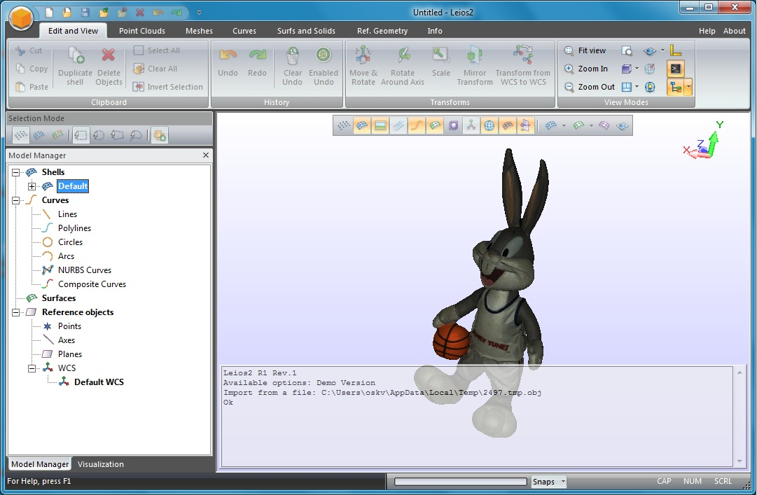
Figure 65 Model exported to Leios
Exporting to Geomagic Design X
Polygonal models created in Artec Studio are insufficient for most design needs. Geomagic Design X (formerly Rapidform XOR) is purpose built to create manufacturing-ready CAD models directly from meshes.
To export a model,
- Make sure Geomagic Design X is installed on your computer
- In the Workspace panel, mark one model using the flag
- Select the Export to Design X command from the File menu
- Wait for the model in
OBJformat to open in the reverse-engineering system.
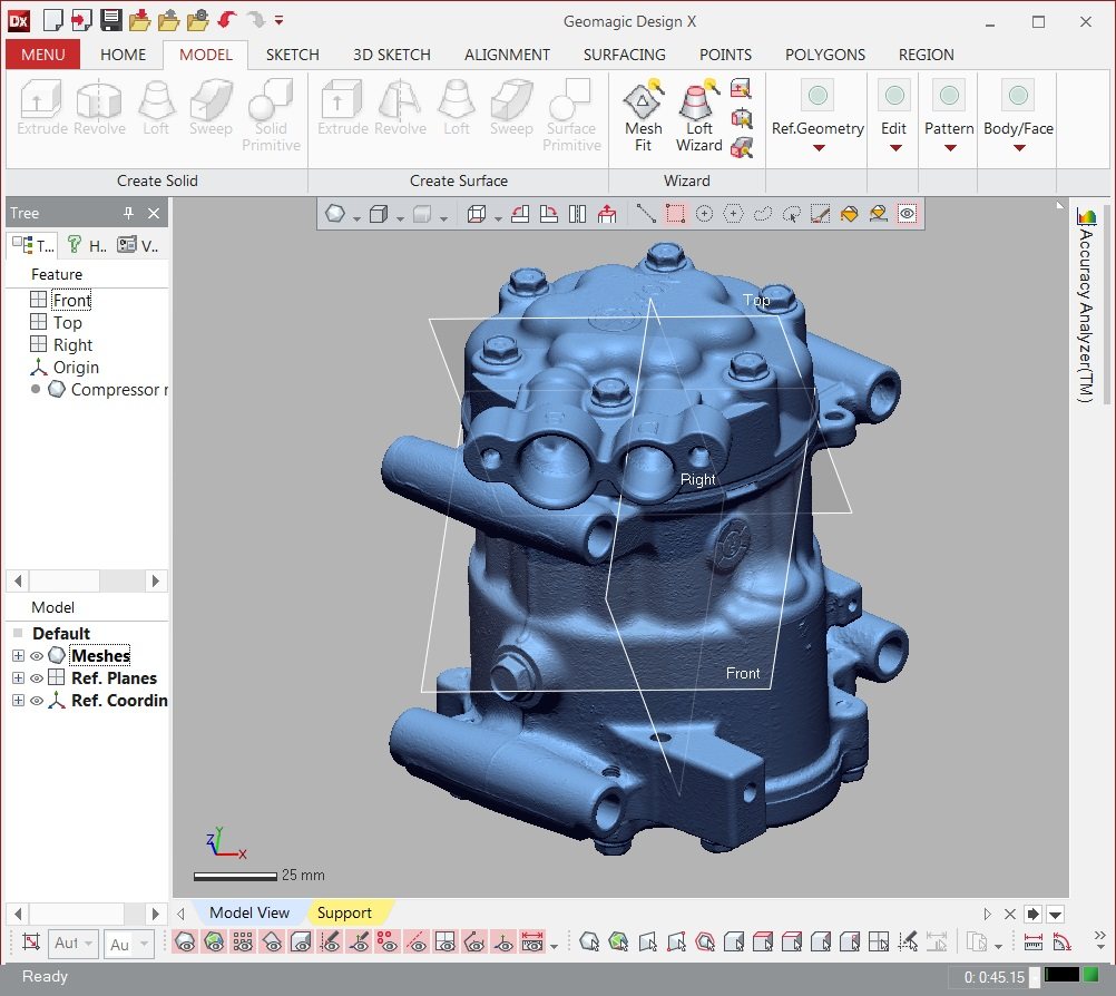
Figure 66 Model exported to Geomagic Design X
Exporting to SolidWorks
Artec Studio allows you to export models to SolidWorks by using third-party plug-ins. It supports the following plug-ins:
- Geomagic for SolidWorks
- DezignWorks for SolidWorks
To export a model,
- Make sure SolidWorks and either of the plug-ins are installed on your computer
- In the Workspace panel, mark one model using the flag
- Select the Export to SolidWorks command from the File menu
- Wait for the model to open in the CAD system.
History of Project Changes
Artec Studio stores all data changes and you can later undo most of them. To undo an operation, click the  button in the Workspace panel. To perform the previously undone operation, click
  . You can also use Ctrl + Z or Ctrl + Y. Use the dropdown menu of commands or , respectively, to undo or redo several operations at once.
When you save a project, Artec Studio stores 3D data together with the history of changes. You can select the maximum length of the history in the settings window under the Performance tab (see Command History). In addition, the Compact memory button allows you to save the history of changes on a local drive and thus free up RAM. Also, the Clear command history button clears the change history, likewise freeing up RAM, and makes the undo operation for the most recent changes unavailable. To clear the history, you can use the Edit → Clear history menu option in the main window or hit Ctrl + Alt + H.
Autosaving a Project
A project can be saved by either the user or Artec Studio. The latter case is called autosaving. For temporary (i.e., unsaved) projects, autosaving is unavailable. The application autosaves a project in the following cases:
Before running the texturing algorithm (see Texturing)
When scanning is complete and the Save scans directly to disk option is selected (see Scanning Procedure)
When unloading scans with unsaved changes (see Selectively Loading Project Data)
When the Save project before starting algorithms setting is selected (see Autosave Options):
- Before launching algorithms from the Tools panel
- Before and after running the Global registration algorithm (Global Registration)
- Before starting Autopilot (Autopilot).