First Steps
Getting Started With Artec Studio
Windows, Panels and Bars
When you launch Artec Studio, you will see the main application window, which allows you to perform all operations on scans and models.
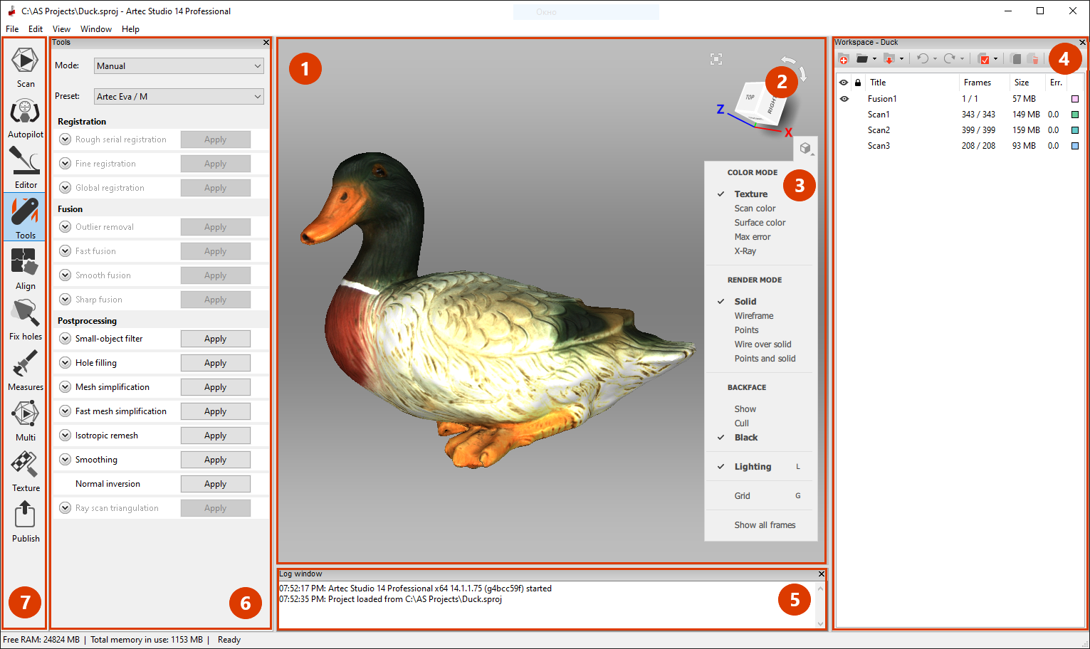
The main window is divided into several sections:
- 3D View
- Navigation cube
- 3D toolbar
- Workspace panel
- Log window
- Left panel (figure depicts optionally open panel Tools)
- Left toolbar
- Not marked in the figure: menu bar (top) and status bar (bottom).
The 3D View window displays all 3D data. You will use this window regularly. When the application launches, a coordinate grid with coordinate axes will appear in the center. Your scans and models will employ this global coordinate system.
To the left of the 3D View window is the left toolbar that contains icons for various application modes, including Scan, Autopilot, Editor, Tools, Align, Fix holes, Measures, Multi, Texture and Publish. These modes are mutually exclusive: the application can work only in one of them at any given time, except for Autopilot. Some modes will lock the Workspace panel when you use them.
To the right of the 3D View window is the navigation cube and the 3D toolbar containing the following commands: Fit to view, Grid, Lighting, Color, Render mode and Backface.
The Workspace panel displays and manages all data uploaded to the application. Here you will find your scans as well as project-manipulation commands, such as saving, erasing, moving and renaming. You can reveal the hidden Workspace panel by clicking  at the top right of the 3D View window.
The Log panel sits at the bottom of the application window. The log is the software’s report on any executed commands, specifying the time and details of each operation. It also stores all error and troubleshooting messages generated by the algorithms.
The status bar contains information on memory availability and current usage by Artec Studio. It also has a progress indicator for any currently running task, such as algorithm execution, model and scan exporting, and so on.
Primary Settings
To access the settings dialog, select Settings… in the File menu. The settings window has several tabs for various groups of application settings. To switch between the tabs, click the icon at the top of the dialog. For a detailed description of the tabs, see Settings.
To change the language, select the Miscellaneous tab (Figure 139) and then the required language from the list and click OK. You will be asked to confirm the operation and restart the application. Once you agree, Artec Studio will automatically restart using the new interface language. If you choose not to restart, the changes will be applied the next time you start the application.
Under the Performance tab you can specify the maximum number of alterations to be saved, or specify maximum the size (in MB) of the history to be saved. The Data-compression level slider enables you to adjust the compression level when saving project data to a disk.
Object Types
After each scanning iteration, Artec Studio saves a separate scan. The list of all scans for a given project appears in the Workspace panel (see Figure 52). Afterwards, the algorithms, primarily Creating Models (Fusion), yield models.
Artec Studio can accommodate the following types of objects in Workspace:
| Type | Content | Origin | Example Name |
|---|---|---|---|
| Scan | Set of frames | From scanners Eva, Spider, Leo and Micro | Eva Scan 1 |
| Point-cloud scan | Point-cloud | From Ray scanner | Ray Scan 1 |
| Model | Polygonal mesh | Algorithm output or imported mesh | Sharp fusion 1 |
Workspace Columns
Data in the Workspace panel is arranged in several columns:
Scan list
 |
Scans marked with in this column will appear in the 3D View window and will undergo processing by all Artec Studio algorithms and tools. |
 |
Algorithms won’t reposition frames of the locked scans (marked with ) |
| Title | When a scan is created, Artec Studio automatically assigns it a name, such as Eva Scan 1, Eva Scan 2 and so on, according to the values in the Scan name and Start with fields as well as the state of the Add scanner type in prefix checkbox in the Scan panel. To rename a scan, select it by left-clicking on its name. Then either hit F2 or right-click on the scan name to open the dropdown menu. Select the Rename… option. Both approaches open a dialog that allows you to specify the new name. |
| Frames | The number of frames loaded into memory along with the total number of frames constituting the scan (see Selectively Loading Project Data) |
| Size | The size of a particular scan (in MB). |
| Err. | The largest registration-error value among all frames in the scan. More information. |
| Color | In this column, each scan has a colored square  next to it. The square’s fill depends on the number of scan frames loaded into the application. When all frames are loaded, the square will be completely filled in. When only key frames are loaded, it will be half filled, and when all the scan data is unloaded, it will be unfilled (see Selectively Loading Project Data). You can change the scan color by clicking on the corresponding square and selecting the desired color from the palette. next to it. The square’s fill depends on the number of scan frames loaded into the application. When all frames are loaded, the square will be completely filled in. When only key frames are loaded, it will be half filled, and when all the scan data is unloaded, it will be unfilled (see Selectively Loading Project Data). You can change the scan color by clicking on the corresponding square and selecting the desired color from the palette. |
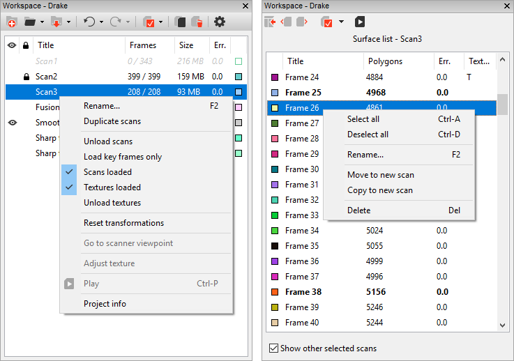
Figure 52 Workspace panel: scan list (original view) on left and surface list on right.
Workspace Toolbar Commands
Toolbar located at the top of the Workspace panel duplicates commands from the menu bar and helps to quickly create  , open
  or save
  project, undo
  operations of the command history, access Settings
  .
.
You can also access project statistics. Call a context menu (RMB) of any object in Workspace and select the Project info command.
Selecting Scans and Models
To view a scan or model in the 3D View window or to process it, you need to mark it with the icon in the Workspace panel. To navigate scans and models, use keys ↑ and ↓ or click an arbitrary area except those in , or color column ().
| Purpose | Method | Alternate Method |
|---|---|---|
| Highlight scan in Workspace | Left-click on the scan name | — |
| Toggle visibility and availability for processing ( flag) |
Left-click in the leftmost column | Hit Space on the highlighted scan or select scan name using Shift+Alt+LMB |
| Batch selection (deselection) of scans for display and processing | Click  |
Hit Ctrl+A (Ctrl+D) |
| Select a single scan for processing and deselect others | Select the scan name using Ctrl+Alt+LMB | Use Ctrl+LMB in the empty area of the leftmost column |
In addition to the methods in the table above, you can use commands from the dropdown menu of the button. See also the full list of hot keys in Workspace.
Selecting Frames
Double-clicking the scan name opens the Surface List panel, revealing all frames in that scan (see Figure 52, right).
Highlighting specific frames will make them (and only them) appear in the 3D View window. When the Show other selected scans option at the bottom of the panel is checked, the selected frames from other scans will also appear in the 3D View window.
You can select frames in a number of ways:
- Click LMB on the frame name to select it while clearing other selections.
- Click LMB while holding the Ctrl key to select several frames at once.
- Click LMB while holding the Shift key to select a sequence of frames in the specified range.
- Click the icon in the Surface list panel to select all frames or to clear the selection.
- Use the dropdown menu for to quickly select all key frames or all textured frames.
- Click Ctrl + A to select all frames.
To start a sequential frame demonstration, use the Play command of the scan context menu,  button in the Surface list or Ctrl + P shortcut. To stop the demonstration, select Stop playback from the scan menu, click
  or hit Ctrl + P again.
Selecting Models
Double-clicking the model that contains no frames will bring a panel with its properties (see Figure 53).
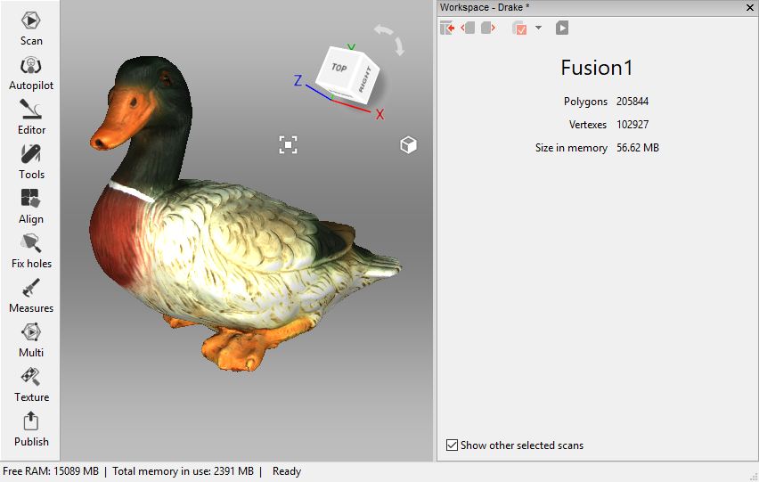
Figure 53 Model properties.
Selecting Point-Cloud Scans
Point-cloud scans contain only one surface. To access scan summary list, double click its name in the Workspace. It includes the following data:
- Polygon and vertex count. Since Artec Studio doesn’t display all the points constituting the scan, you can only see a mesh obtained from a simplified copy of the actual point cloud.
- Points in point cloud Total number of points.
- Sections in point cloud. When you scan with Ray, you may select particular regions (sections) to narrow down the actual scene. This parameter stands for the number of these regions.
Context menu for a point-cloud scan has the Go to scanner viewpoint command that moves camera to the exact position where Ray captured this scan.
Memory Management and History
Selectively Loading Project Data
When working with a large data set, you may often find it necessary to free up RAM without deleting any of the project data. To this end, Artec Studio implements a mechanism for selectively loading scans. You can move to disk any currently unused scans to free up extra RAM. If a particular algorithm later requires any of the unloaded scans, the application will automatically reload them. Frames that are not currently loaded into the memory won’t show in the 3D View window.
Any scans or frames that are completely unloaded from memory will appear in a gray italicized font in the Workspace window (see Figure 54).
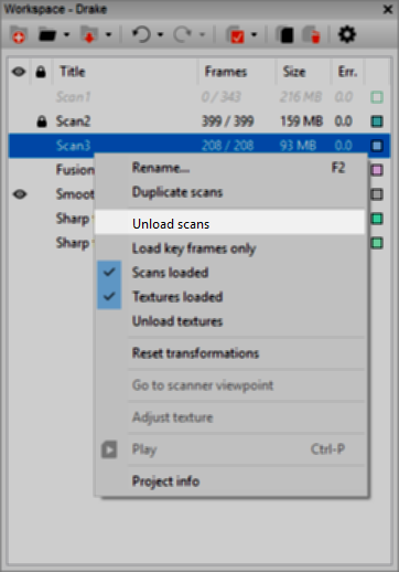
Figure 54 Selectively unloading scans.
Note
Before you can change a scan’s loading status, you must save the project.
To change the loading status, select the scans in the Workspace window (using the Ctrl key), click RMB and then select one of the scan-loading options in the pop-up menu (see Figure 54):
| Menu Command | Function | Resulting Icon Appearance |
|---|---|---|
| Unload scans | Fully unload scans from memory |  |
| Load key frames only | Only load key frames into memory |  |
| Load scans | Fully load scans into memory | |
| Load textures | Fully load texture images into memory | — |
| Unload textures | Fully unload textures from memory | — |
| — | Scan loaded partially (some frames not loaded) |  |
Algorithms may automatically change the loading status of project data in the following cases:
- You have selected unloaded scans for processing by clicking the button. Artec Studio will load these scans into memory.
- Execution of the algorithm requires large amounts of memory. Artec Studio will unload unused scans, frames, textures or a combination thereof.
- Algorithm needs certain frames and it loads only them.
Note
In addition to 3D data, the change history can also consume a large portion of memory. For information on how to control the history size as well as how to unload or clear it, consult History of Project Changes.