Scanner Calibration and Correction
The Diagnostic Tool is a special utility that enables you to calibrate Artec 3D scanners and correct an existing calibration. In general, calibration is the process of checking and adjusting a scanner’s measurements by comparing them with the standard (etalon) values. Every Artec scanner is delivered pre-calibrated.
In some cases, owing to careless handling or transportation (jolts, accidental drops or some other reason), the scanner may fail to capture surfaces properly. The scanned surfaces may only be partially reconstructed or may contain holes (for example, the results of bad reconstruction are noticeable on the blue surface in Figure 162). You can resolve these issues by correcting or calibrating the scanner.
Depending on the scanner model, the Diagnostic Tool can operate in one of the three working modes:
- Correction for Artec MHT, Artec MH, Artec L and Artec EVA scanners
- Correction for Artec Spider scanner
- Calibration of Artec Spider scanner
Note
Calibration is available only for Artec Spider scanners.
Suggestions for Use
Correction differs from calibration in that it preserves the current calibration: it only changes the correction ratio so as to enable good reconstruction.
Important
Application of the correction does not guarantee that captured geometric shapes and linear measurements will be accurate. Use this procedure as a temporary measure until calibration is performed.
| Mode | Characteristics | Speed | For Spider? | For EVA, L, MHT? |
|---|---|---|---|---|
| Correction | Inexact | Fast | Yes | Yes |
| Calibration | Exact [1] | Prep required | Yes | No |
| [1] | Restores the device to its original factory settings. |
Launching Diagnostic Tool
To launch the Diagnostic Tool, first ensure that the scanner you intend to diagnose appears in Artec Installation Center as either On loan or Activated. You can launch the tool either through the Start menu by clicking or in Artec Studio by selecting the Run Diagnostic Tool command from the File menu.
If you have several scanners connected, select the appropriate one from the dropdown list.
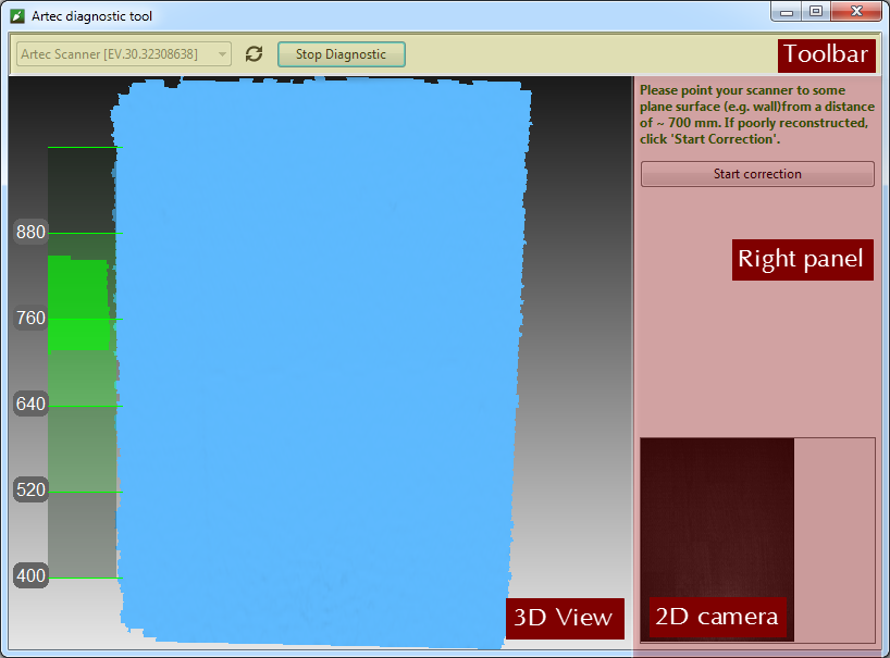
Figure 158 Diagnostic Tool window.
The utility window contains three sections: the 3D View panel, the right panel and the toolbar (see Figure 158).
Scanner Correction
Important
Apply correction sparingly as a temporary measure until calibration is performed.
Correcting Field of View for EVA, MHT, MH and L Scanners
The Artec EVA, Artec MHT, Artec MH and Artec L scanners only allow you to correct their current calibration data on field of view.
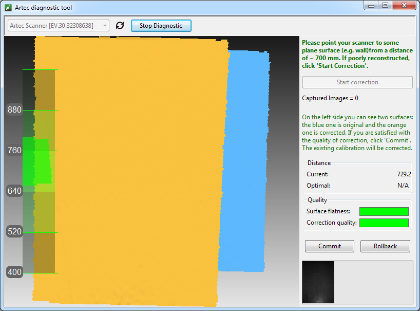
Figure 159 Artec EVA correction results.
Launch the Diagnostic Tool as Launching Diagnostic Tool describes.
Select the scanner you want to diagnose.
Click Start diagnostic or press the
 button. The scanner will start the preview, a range meter will appear in the 3D View window and another panel will appear on the right showing a 2D camera preview.
Direct the scanner at the right angle to a flat, light (but not shiny) monochrome surface (e.g., a wall or floor) from a distance of 650–700 mm for an Artec MHT, Artec MH or Artec EVA scanner or a distance of 850–900 mm for an Artec L scanner. The tool will render the surface in blue in the 3D View window.
Note
If the rendered surface is not flat and contains holes, the correction is worth performing.
Click Start correction or press the
button on the scanner. In addition to the blue surface, a yellow surface will appear in the 3D View window. Blue corresponds to the surface captured using the original calibration data; yellow corresponds to the surface captured using corrected calibration data.Two indicators in the right panel can help you assess the surface quality (green stands for good results, yellow for satisfactory and red for unsatisfactory). If the corrected (yellow) surface has no holes and is sufficiently flat, and if the correction results meet your expectations, click Commit or press the
button on the scanner. Otherwise, click Rollback or press  on the scanner.
Correcting Calibration Data for Spider
Correction for Artec Spider differs slightly from correction for Artec MHT and Artec EVA scanners.
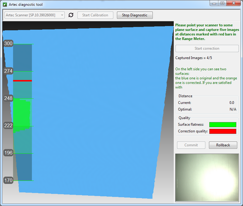
Figure 160 Artec Spider correction process.
Launch the Diagnostic Tool as Launching Diagnostic Tool describes.
Select Artec Spider from the dropdown list.
Click Start diagnostic or press the
button; the scanner will start the preview, a range meter will appear in the 3D View window and another panel will appear on the right showing a 2D camera preview.Direct the scanner at the right angle to a flat light monochrome surface (e.g., a wall) from a distance of 190–270 mm. The tool will render the surface in blue in the 3D View window.
Note
If the surface, when captured from a distance within the suggested range, fails to render as flat or contains holes, correction is worth performing.
Place the scanner on a desk or attach it to a tripod, keeping a distance of about 190 mm from the flat surface (see the range meter in the 3D View window).
Click Start correction or press the
button on the scanner. A red mark will appear on the range meter.Move the scanner smoothly toward the flat surface such that the histogram peak coincides with the red mark on the range meter (see Figure 161).
Look for a new red mark to appear higher on the range meter. Smoothly move the scanner away from the flat surface to approach the red mark.
Repeat Step 8 three more times. Once you finish, the calculation will start. A yellow plane that corresponds to the surface you captured using the corrected calibration settings will then appear in the 3D View window (see Figure 162).
If the yellow surface has no holes and is sufficiently flat, and if the correction results meet your expectations, click Commit or press the
button on the scanner. Otherwise, repeat Steps 7–9, click Rollback or press on the scanner. Two indicators on the right panel can help you assess the surface quality (green stands for good results, yellow for satisfactory and red for unsatisfactory).

Figure 161 Artec Spider scanner’s position and corresponding distance on the range meter.

Figure 162 Artec Spider correction results.
Spider Calibration
To carry out the calibration, you will need the following additional equipment: a calibration rig, a scanner stand and a pattern. Assembly instructions for the scanner stand and calibration rig appear in Assembling the Scanner Stand and Assembling the Calibration Rig, respectively.
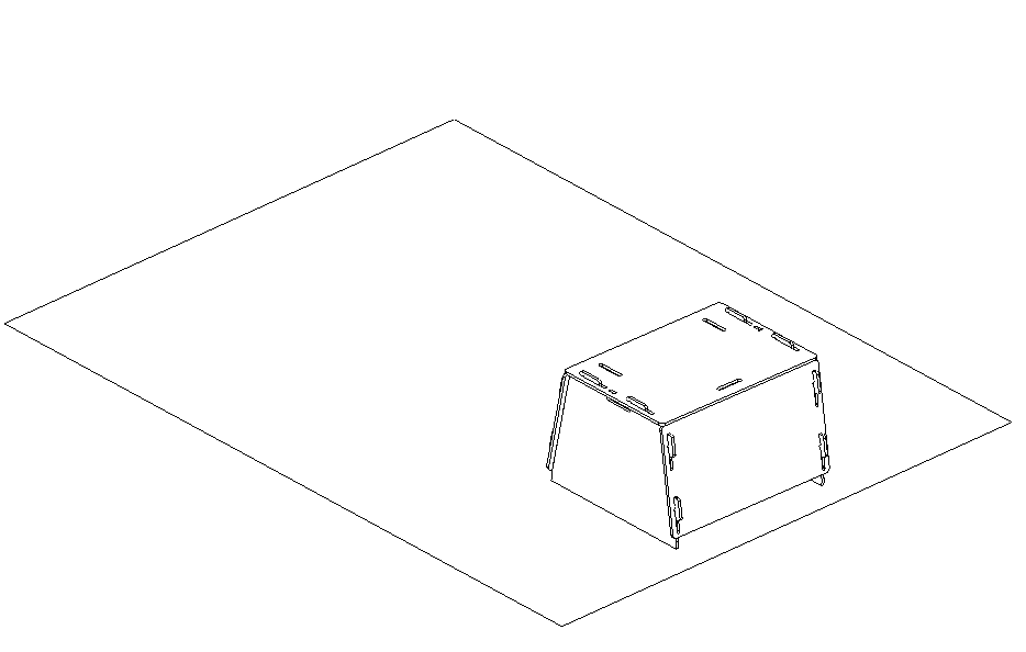
Figure 163 Scanner stand resting on a pattern.
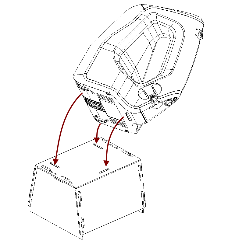
Figure 164 Placing Artec Spider on the stand
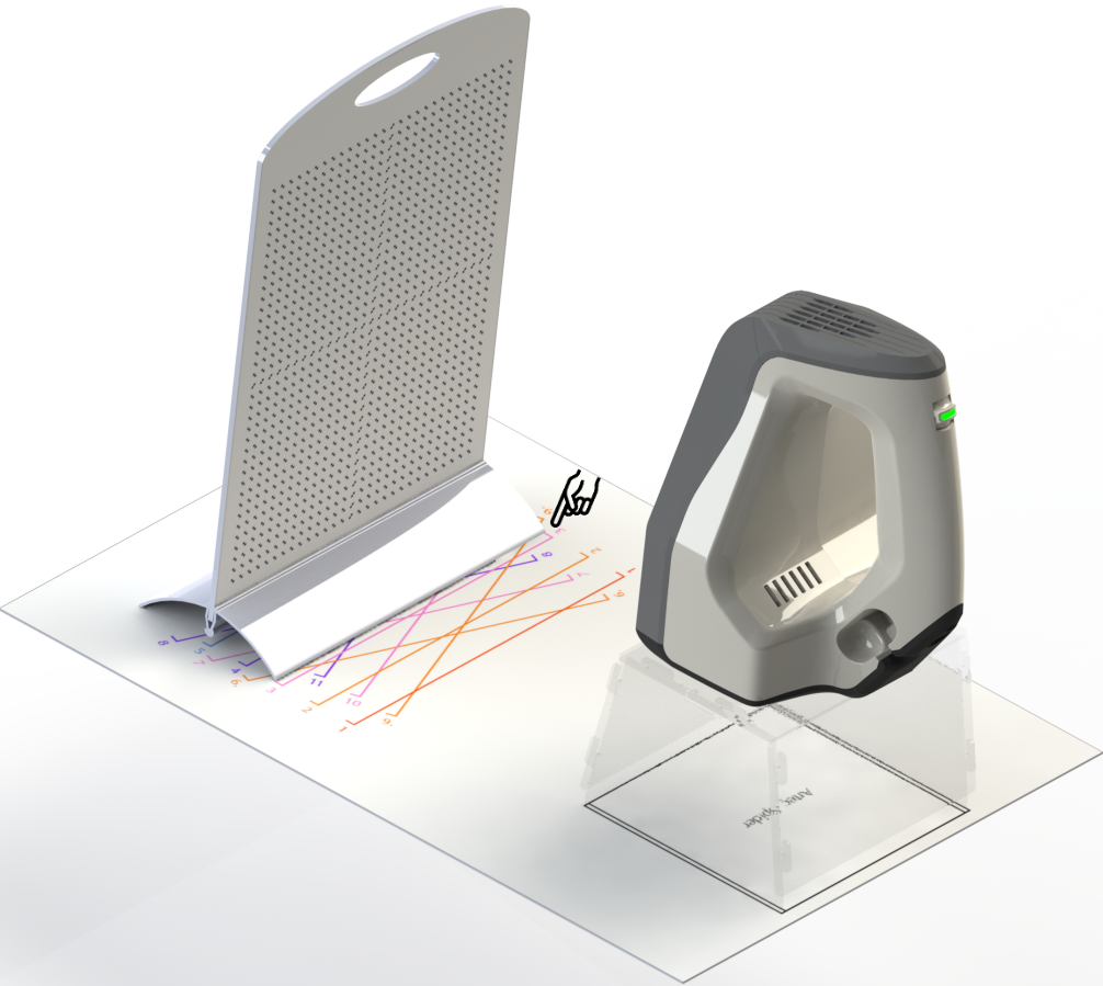
Figure 165 Calibration rig, pattern and scanner stand with Artec Spider.
Unfold the pattern and place it on a desk or any hard, planar surface.
Align the scanner stand with the rectangle marked on the pattern, paying close attention to the orientation of the slots in the stand cover (see Figure 163).
Place the scanner on the scanner stand, making sure that you insert the three scanner stems in the three slots of the stand cover (see Figure 164).
Set the calibration rig on the pattern, turning its marker side toward the scanner as Figure 165 shows.
Launch the Diagnostic Tool as Launching Diagnostic Tool describes.
Note
You should conduct the calibration only after the scanner has warmed to the optimal temperature.
Click Start calibration. A dialog box will open (see Figure 166); enter the serial number of your calibration rig (it appears on the board). If the scanner temperature is outside the optimal range—for example, you just connected the device to a power outlet—the tool will notify you of this condition (see Figure 167). We advise against clicking Skip and instead recommend waiting for the Artec Spider to reach its optimal temperature.
Place the rig in its initial position such that the front edge of its base coincides with the color line numbered 1 on the pattern. As you do so, also keep an eye on the 3D View window for a red plane (current position) and a green plane (target position)—see Figure 168. Once the red plane coincides with the green one, stop moving the rig and wait for the scanner to capture the plane.
Wait for the tool to instruct you to move the rig to the next position on the pattern; the number for that position will appear on the screen. Move the rig and again wait for the scanner to capture the plane.
Repeat the preceding step for the remaining positions sequentially. Depending on the version of your calibration kit, the pattern will have 11 to 15 positions.
Once you have captured the last position and the calculations have concluded, a message will appear prompting you to either overwrite the existing calibration or keep the current one. Before you decide, direct the scanner at a flat, nonglossy surface (e.g., a piece of paper) from a distance of about 200 mm. Assess the quality of the reconstructed surface and check for any holes.
Click Yes, apply the calibration if no holes appear on the surface and you are satisfied with the reconstruction results. To reject the new calibration, click No, keep the old one (see Figure 169).

Figure 166 Entering serial number of calibration board.
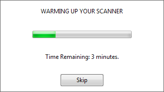
Figure 167 Warming up the scanner.
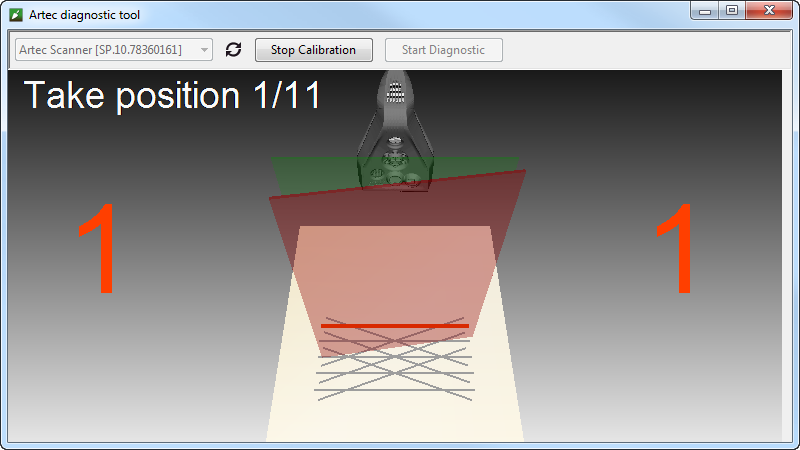
Figure 168 Moving calibration rig to position number 1.
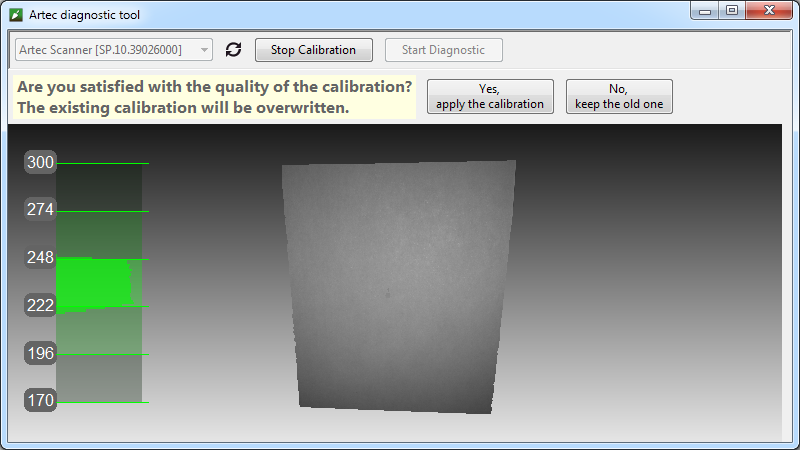
Figure 169 Assessing calibration results.
Notes Regarding Scanner-Calibration Files
Calibration and correction results reside in files that you can access as follows. Their location is
C:\Users\%name%\AppData\Roaming\Artec\Artec Installation Center
\Devices\SP.00.00000000.
Here, %name% is the current user folder and SP.00.00000000 is the folder corresponding to the scanner serial number. Note the following information regarding calibration and correction.
- Once you apply correction results, the software will create an
ACDfile. - Once you apply calibration results, the software will create
ACDandCORRfiles. - All newly created files have names of the form
YYYYMMDD_HHMMSS, with the characters corresponding to the date and time of the file’s creation. - Original
ADDandCORRfile names are based on the scanner serial number and have the formSP.00.00000000.
Note
You can restore the initial calibration by removing the ACD and CORR files whose names have the form 20131121_101010.
Note
If you use the scanner on several computers, you need not recalibrate it on every one. Simply copying the ACD and CORR files to the above-mentioned folder on each computer may be sufficient.
Assembling the Scanner Stand
The scanner stand comes unassembled with Artec Spider and consists of five parts (see Figure 170): two side walls, one front and one back wall (these parts are identical, however), and a cover. Before beginning assembly, lay them all out as Figure 170 shows. Then follow these steps:
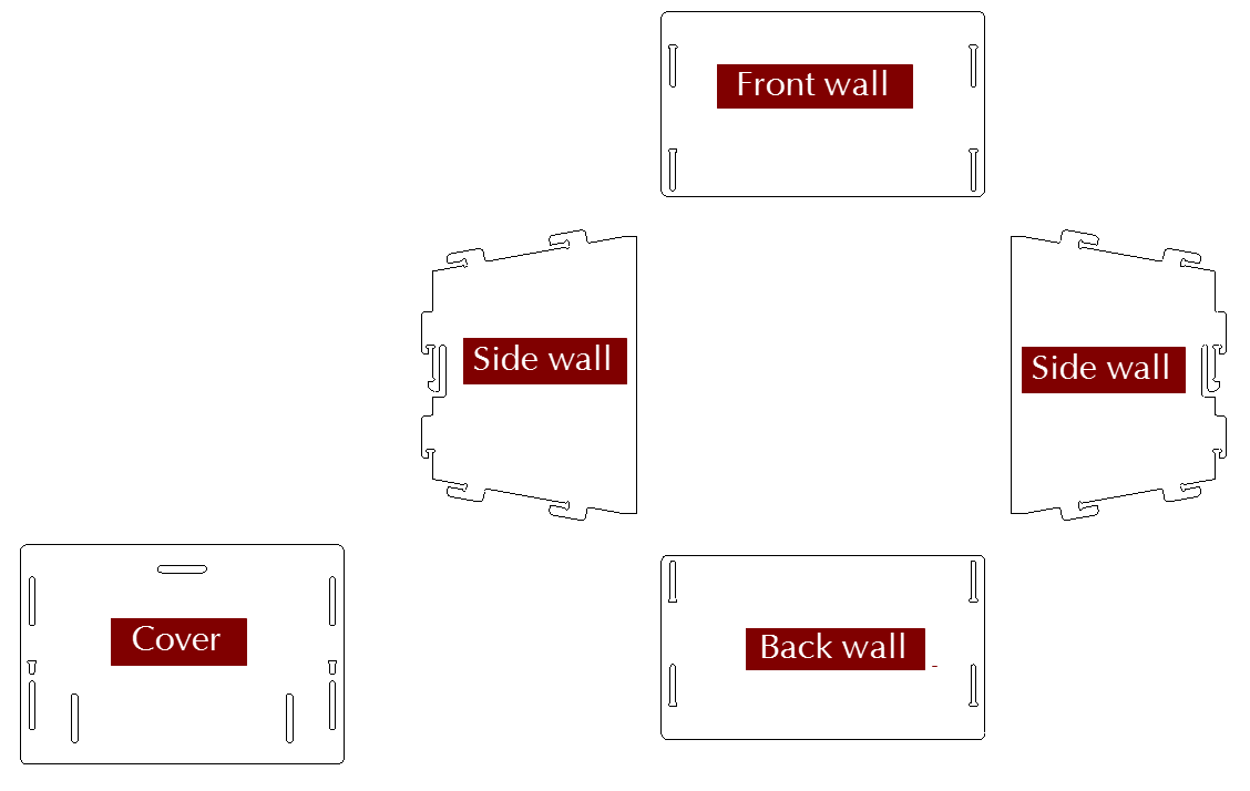
Figure 170 Parts of the scanner stand.
- Raise the two side walls to the upright position, as Figure 171 shows. Noting carefully the orientation of the T-shaped slot, install the front wall to the side walls using the two pairs of hooks. Press the front wall and slide it down against the stop. Make sure the three walls are properly aligned with each other.
- Install the back wall in the same way (see Figure 172).
- Paying attention to orientation of the slots, install the cover using the upper hooks of the side walls (see Figure 173).
- Press your thumbs against the T-shaped holes on the cover and shift it toward the back wall until you hear a click (see Figure 174).
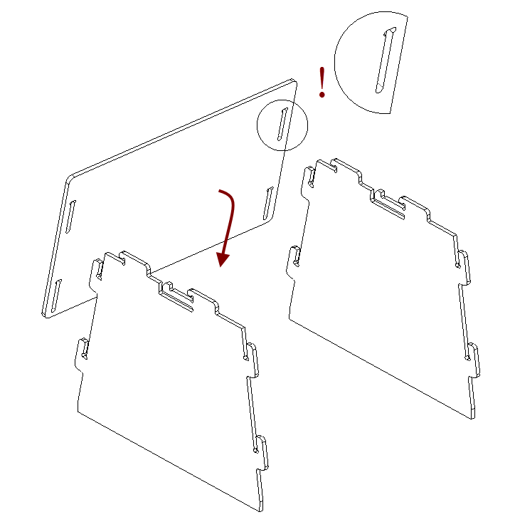
Figure 171 Assembling the front wall.
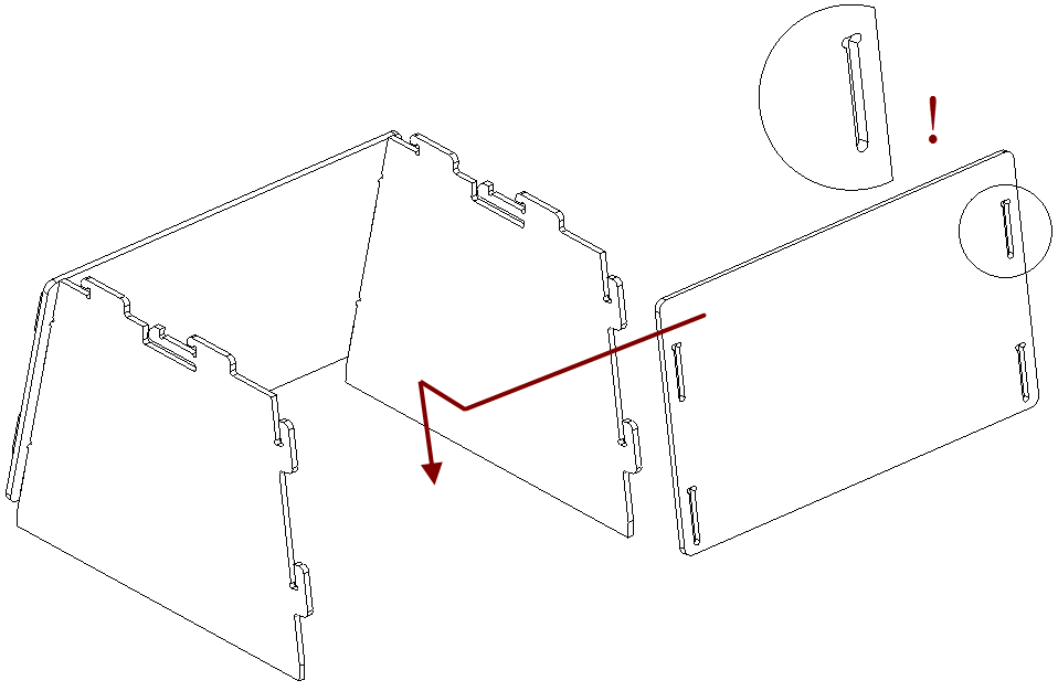
Figure 172 Assembling the back wall.

Figure 173 Mounting the cover.

Figure 174 Latching the cover.
The scanner stand is now ready to use.
Note
To disassemble the stand, release the detents in the cover’s T-shaped slots (see Figure 170) using a thin object like a ballpoint pen. Repeat the assembly steps in reverse order (from Figure 174 to Figure 171), moving the parts in the opposite directions.
Assembling the Calibration Rig
The calibration rig comes only with Artec Spider and consists of the base and the board. To assemble the rig, follow these instructions:
- Press the hinge of the base against your forefingers.
- Unfold the bent leaves of the base, pressing on their edges with your thumbs.
- Insert the board into the slot, as Figure 175 shows.
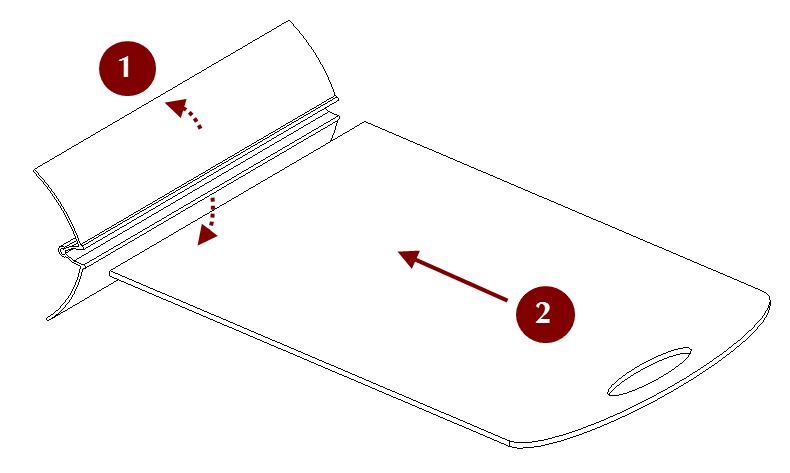
Figure 175 Assembling the rig.