Working with CAD objects
Starting from version 15, you can work with CAD objects in Artec Studio. You can either create CAD primitives and then export them into CAD files or import CAD objects designed in external applications. This allows you to:
Modify and design new parts for existing objects;
Reverse engineer scanned objects;
Ensure quality control by comparing scanned objects to their CAD models.
Starting from version 17, Artec Studio supports two kinds of CAD primitives that differ in the way they are created:
Fitted CAD primitives that Artec Studio fits into the selected part of a mesh (model);
Independent CAD primitives that are created independently on the model.
CAD Primitives Types
At present it is possible to construct the following types of primitives:
Cylinder,
Cone/Truncated cone,
Sphere,
Plane,
Torus,
Box.
A torus is a donut-like figure, which is determined by the radii of its outer and inner circumferences: major and minor radii, respectively.
There is also another type of the fitted CAD primitives called surfaces:
Freeform patch,
Autosurface.
A freeform patch can be thought of as a sheet of paper that you wrap around the portion of the object’s surface. The freeform patch can be used for complicated surfaces that are not covered by usual types of primitives, such as surfaces of organic objects, for example. The following parameters are required for constructing a freeform patch:
Padding — the percentage by which the selected surface area is expanded before building the patch.
Number of points — the number of control points (patch mesh nodes) on each axis of the patch.
Order — the order of splines used for building the patch.
Note
The more points and the higher the order of splines, the more detailed surface curvature and the closer fit to your model you can get. However, you need to keep in mind that increasing the number of points and the order of splines requires more CPU time for fitting the primitive.
Constructing CAD Primitives
You can construct two kinds of CAD primitives: fitted and independent ones.
See also
Constructing Fitted CAD Primitives
Fitted CAD primitives are constructed on the basis of polygonal meshes (models) and then are fitted into the latter.
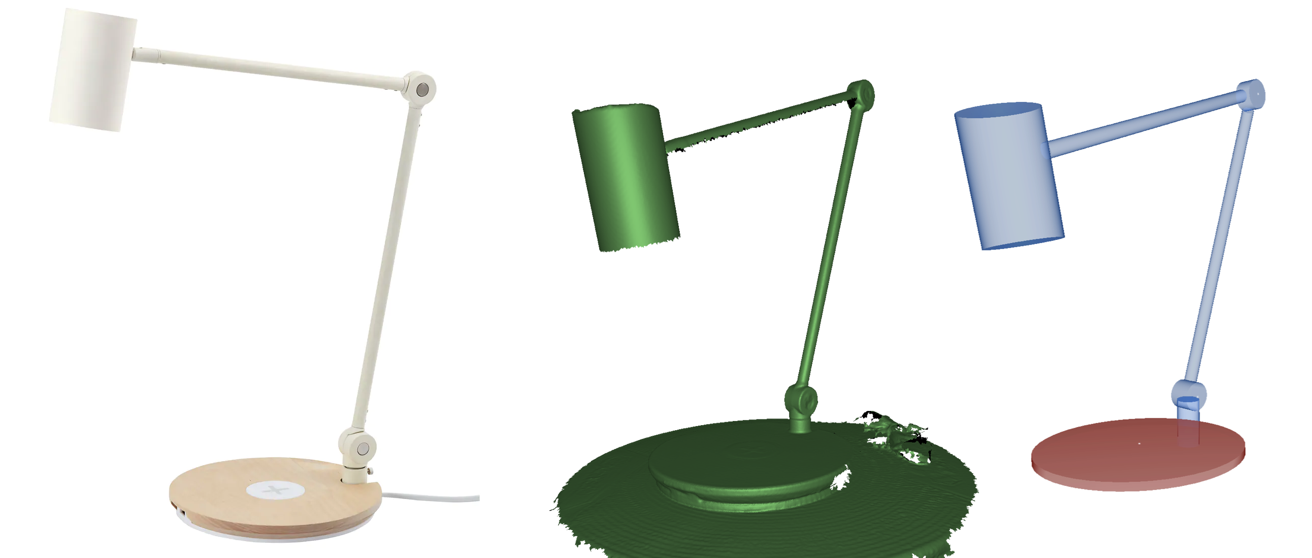
Figure 138 From left to right: original object, scanned model, a set of constructed primitives.
Autosurface allows you to build a CAD primitive in the form of a surface that partially or completely covers the model. The autosurfaces address the problem of quick transformation of organic shapes into CAD objects, as well as the problem of approximating massive meshes with CAD objects suitable for further use in CAD software packages.
An autosurface is constructed as a set of patches of approximately the same size. The number of patches is set by the eponymous parameter. The form of patches can be adapted by the Allow T-Nodes parameter.
Note
The suitable number of patches depends on the size of the selected part of the object’s surface and the number of polygons in the original mesh. For massive meshes with a high number of polygons, more CPU time for constructing the autosurface is required.
Note
An autosurface model can be exported to an external CAD software as a CAD model.
To construct a fitted CAD primitive, follow these steps:
Load a polygonal model in which you will fit the CAD primitive.
Open the Construct panel. The Fit tab will be opened.
Select one of the available primitive types you want to construct (in the example below it is Cylinder).
Choose Selection type and specify the required area on the model:
2D brush (
 ) and 3D brush (
 ) slightly differ in how they work: the former is circular and marks the model surface on the basis of the current viewpoint, whereas the latter is sphere-shaped and selects the surface that falls inside that sphere. Use the Brush size slider to change the brush size.
Lasso (
 ) allows you to specify a polygon on the surface of the model by clicking the vertices of that polygon. A surface is selected that falls inside it.
Lasso (
) and 2D brush () allows you to select the model’s backface using the Select through checkbox.Segment (
 ) is the most convenient of the selection tools. It automatically expands the area you mark with your brush and shows you the result. Thus, you can evaluate which of the regular primitives Artec Studio identified. This selection tool has two settings available: the Brush size slider to adjust the size of your brush and the Segmentation sensitivity slider to adjust the degree of expansion of the area marked with your brush (the higher the sensitivity, the more Artec Studio will expand the marked area).
Note
The Segment option is not recommended for the Freeform CAD primitive or for simplified models (models with fewer polygons).
To select an area on the model, use Ctrl+LMB above the model surface. To deselect, use Alt+LMB above the selected area.
To clear the current selection partially, use Ctrl+Alt+LMB above the selected area.
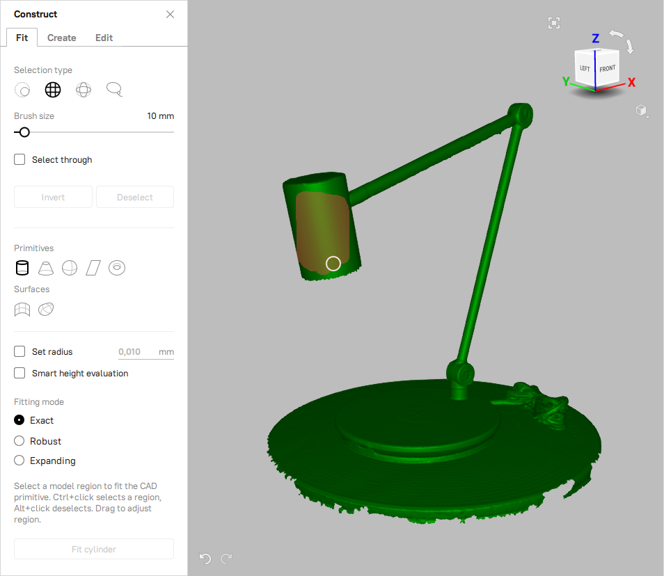
Figure 139 The Fit tab of the Construct panel: specifying the area using the 3D brush.
Use the Invert button to invert selections, and also use the Deselect button to reset all the selections you made.
Note
When you create an Autosurface CAD primitive, it can cover the model partially or completely. If you select an area on the model, the primitive will only approximate the marked area. If no area is selected, then the entire model will be approximated.
Once the required area has been selected, choose a Fitting mode:
Expanding mode requires the user to mark just a small spot on the object. The algorithm will search the model corresponding to the shape of the selected primitive, and fit the primitive at the borders of the found location.
Robust mode works with the area that the user has selected. However, if there are any conflicting surfaces, the “Robust fit” will ignore them and will work with the largest selected area.
Exact mode only works on the area the user has selected. The algorithm allows you to select custom areas for a future primitive and control its size, even if the object isn’t exactly primitive-shaped.
Note
It is not recommended to use the Expanding mode with the Segment selection tool as their implementing algorithms contradict to each other.
Note
The Fitting mode is not applied to the surfaces.
Click the required primitive icon on the Primitive type bar.
If the selected primitive (sphere, cylinder or truncated cone) should fit into a hole of a given depth, such as a hole in a plate, then check the Smart height evaluation option. In this case, Artec Studio will use an algorithm that provides a more accurate fitting of the primitive to the model.
If necessary, specify the desired parameters of the primitive to be created:
For a cylinder or sphere — its radius
For a cone — its angle and Truncated checkbox
For a torus — its major and minor radii (find the description above in this section)
For a freeform patch — padding, number of points, and order (find the description above in this section)
For an autosurface — number of patches (see CAD Primitives Types for the description) and Allow T-nodes checkbox
Click Fit cylinder button (or Fit sphere, etc.) to confirm your choice. Artec Studio will create a CAD primitive and fit it into the selected area.
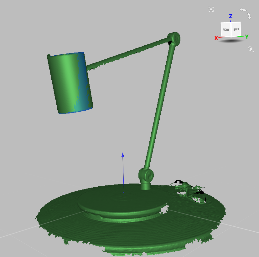
Figure 140 Cylinder (blue) fit into the model.
Constructing Independent CAD Primitives
To construct an independent CAD primitive, follow these steps:
Open a new project or load a polygonal model which you will modify with the CAD primitive.
Open the Construct panel and go to the Create tab.
Select one of the available primitive types you want to construct (in the example below it is Cylinder).
Specify the parameters of the CAD object to be created:
For a cylinder—its radius and height
For a cone—its radius, height, aperture, and Truncated checkbox
For a sphere—its radius
For a plane—its width and height
For a torus—its major and minor radii (see CAD Primitives Types for torus description)
For a box—its width, length and depth
Position the CAD object as needed.
To move the primitive, click and drag the appropriate gizmo control while the Translate tab is active.
To rotate the primitive, click and drag the appropriate gizmo control while the Rotate tab is active.
You can also specify the translation of the object and its axes rotation changing the corresponding parameters in the Translate and Rotate tabs respectively.
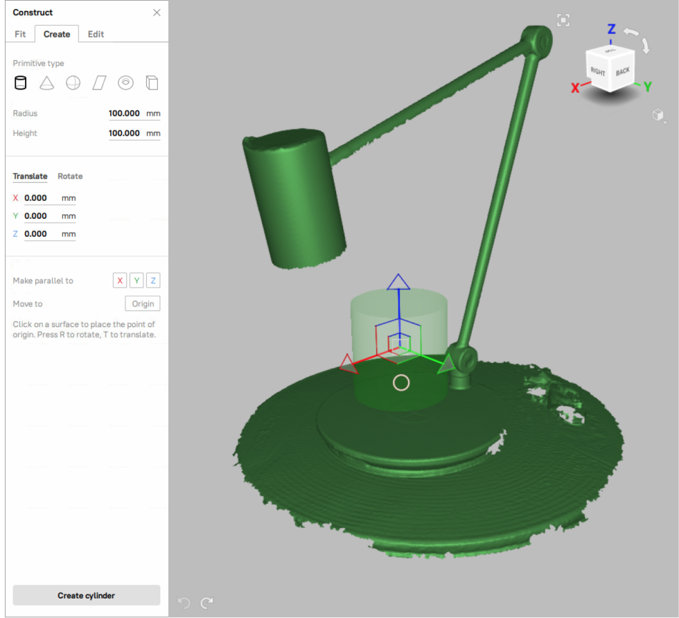
Figure 141 The Create tab of the Construct panel: specifying the CAD cylinder parameters.
Click Create cylinder button (or Create sphere, etc.) to confirm your choice. Artec Studio will create a CAD primitive and position it as specified.
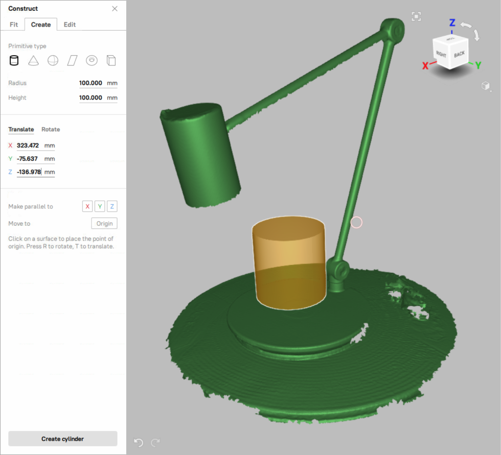
Figure 142 Constructed cylinder (orange).
Note
Make sure that the CAD primitive is positioned properly before creating it. Once it is created, its position will be fixed and you will not be able to change it.
CAD Primitive Properties
To see the properties of the created CAD primitive, do the following:
Click the name or the icon of the primitive in the Workspace panel.
At the bottom of the Workspace panel, click the Properties section to expand it.
The presence of certain geometric parameters in the Properties section will depend on the type of the selected CAD primitive (see table below).
For the freeform primitives the Properties section displays:
U and V points count — the number of nodes along the axes of the primitive
U and V order — the order of splines used for constructing the primitive
Converting CAD to Mesh
It is possible to convert CAD models and CAD primitives to a mesh in Artec Studio (17 and above).
To convert CAD to mesh,
Select the CAD object you want to convert in the Workspace and right-click on it
Then, select the :guilabel:`Convert to mesh ` option in the drop-down menu
Artec Studio then converts the CAD to a mesh (PLY). The original CAD object remains intact too.
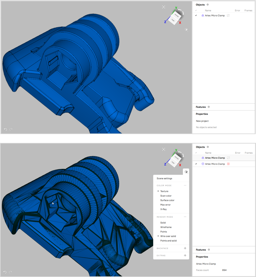
Figure 143 CAD model converted to a mesh.
Setting constraints for CAD primitives
After creating CAD primitives, you can adjust their size and relative position by applying various constraints to them. Artec Studio supports the following kinds of constraints: conditions (they are set for one primitive) and relations (they are set for two or more primitives). Below see the table of available constraint types.
Icon |
Kind of constraint |
This constraint … |
Applicable to … |
|---|---|---|---|
|
Relation |
requires the axes (or normals) of the selected primitives to be parallel |
cylinder, cone, plane, torus |
|
Relation |
requires the axes (or normals) of the selected primitives to be perpendicular |
cylinder, cone, plane, torus |
|
Relation |
sets a given angle between the axes (or normals) of the selected primitives |
cylinder, cone, plane, torus |
|
Relation |
requires the selected primitives to be coaxial |
all types of primitives except plane |
|
Condition |
sets a given value for one of the sizes of the selected primitive, for example, cylinder radius/height, torus minor/major radius, etc. |
cylinder, cone, sphere, torus |
|
Relation |
requires the selected sizes of the selected primitives to be equal |
cylinder, cone, sphere, torus |
|
Condition |
prohibits changes to the primitive during the Refit operation |
all types of primitives |
Note
Independent CAD primitives, as well as Freeform and Autosurface CAD primitives do not support any constraints.
You can set several different constraints for each primitive. There is no limit to the number of constraints.
Note
You cannot set constraints for CAD primitives created in Artec Studio version 16 and earlier.
Applying constraints to CAD primitives consists of two stages. First, you specify the desired constraints, and on the second stage, you force Artec Studio to rebuild the primitives to meet the constraints you set (the refitting process).
To specify and apply constraints to CAD primitives, follow these steps:
Open the Construct panel and create the CAD primitives you need (see Constructing CAD Primitives for details).
Click the desired primitive. The Constrain pop-up toolbar appears with icons for the applicable constraint types (see an example of such a toolbar for the case of a cylinder in Figure 144, a and Figure 145, a).
Note
If you are having difficulty selecting a CAD primitive, you can hide other objects in the 3D View area that may interfere, i.e., meshes, scans, imported CAD models.
Click the icon of the desired constraint type.
Perform the appropriate actions depending on the constraint type you selected:
For
 (lock), no actions are required.
For
 (set length), click one of the icons of primitive sizes on an additional pop-up tool bar if it appears (see an example in Figure 144, b). Specify the desired primitive size value and click
  on the appropriate pop-up toolbar (see Figure 144, c).
For
 (parallel to …),
  (perpendicular to …),
  (at angle to …), and
  (coaxial to …), click all other primitives to be involved into the new relation (see an example in Figure 145, b). When done, click on the appropriate pop-up toolbar (see Figure 145, c).
For
 (equal to …), select one of the primitive sizes on an additional pop-up toolbar (it appears if two or more sizes are available). Then click the second primitive and select one of its sizes. To establish an equality relationship between the two selected sizes, click on the appropriate pop-up toolbar.
The corresponding constraint icon will be displayed next to each primitive participating in the constraint but no changes to the size or position of the primitives will occur at this point (see examples in Figure 144, d and Figure 145, d). A pop-up toolbar with the Refit button will appear at the top of the 3D View window.
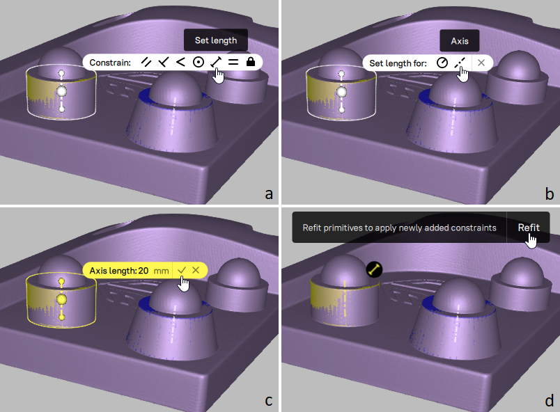
Figure 144 Example for specifying CAD primitive constraints: setting the height of a cylinder.
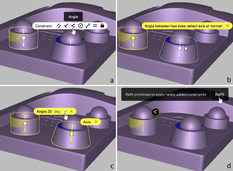
Figure 145 Example for specifying CAD primitive constraints: setting the requirement that the axes of two primitives are at a given angle to each other.
Repeat steps 2 to 4 to add more constraints if required.
Before proceeding to the next step, you can click the icon of any constraint and make the necessary changes or remove it by clicking
 on the constraint’s pop-up toolbar.
To apply the newly added constraints to the CAD primitives, click the Refit button on the panel at the top of the 3D View window.
The primitives will be rebuilt to satisfy the specified constraints. Figure 146, b presents the result of applying both constraints illustrated in Figure 144 and Figure 145.
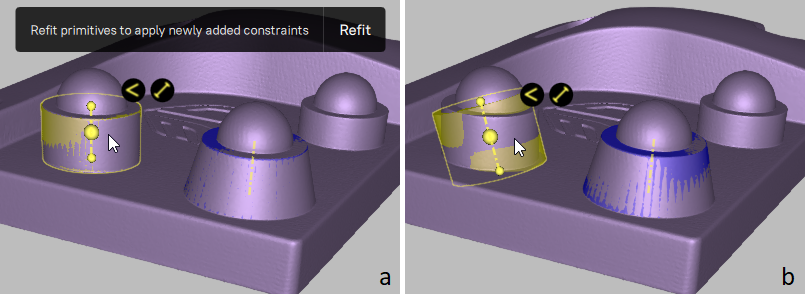
Figure 146 Example for applying CAD primitive constraints.
Note
If the constraints are applied successfully, the symbols in their icons remain yellow, otherwise—the symbols turn red.
If red constraint icons appear as the result of step 7, follow step 6 to change or remove such incompatible constraints, and then repeat step 7 if necessary.
Note
Actions with constraints, as well as the Refit primitives command triggered by the Refit button are recorded in History and can be undone or redone (for example, using the Undo and Redo buttons).
To add more constraints, repeat the above procedure (steps 1 to 8).
To modify the constraints applied to your CAD primitives, perform steps 6 to 8 of the above procedure before closing the Construct panel. You can also switch to the Show CAD constraints mode to view and modify constraints without the Construct panel. To turn it on, use the View → Show CAD constraints menu command.
To cancel the constraints applied to CAD primitives last time you pressed the Refit button, use the Undo command. The previous state of the involved CAD primitives will be restored, however, the constraints themselves will remain unchanged.
To remove a constraint, click its icon and then on the constraint pop-up toolbar. In this case, the result will be the following:
The constraint will be removed.
The CAD primitives participating in this constraint (their size, position, orientation) will not be affected.
Ambiguity of some constraints
For some relations, the result of applying the constraint is ambiguous. For example, the condition that the axis of one primitive is directed at an angle to the axis of another one is not enough to determine the direction of the axes. This problem has an infinite number of solutions. In this case, Artec Studio will choose one of the solutions. For the solution to be unambiguous, additional constraints must be used.
Let us explain this with the following example. Suppose we have two primitives: a cylinder and a plane (see Figure 147, a), and we would like to adjust the position of the plane so that its normal becomes perpendicular to the axis of the cylinder. For this, we specify and apply the corresponding constraint (). The result obtained after refitting the primitives is shown in Figure 147, b. It is correct, but not what we expected. To get the desired result, we need to set an additional constraint, for example, we can lock the cylinder for changes (see the corresponding result in Figure 147, c).
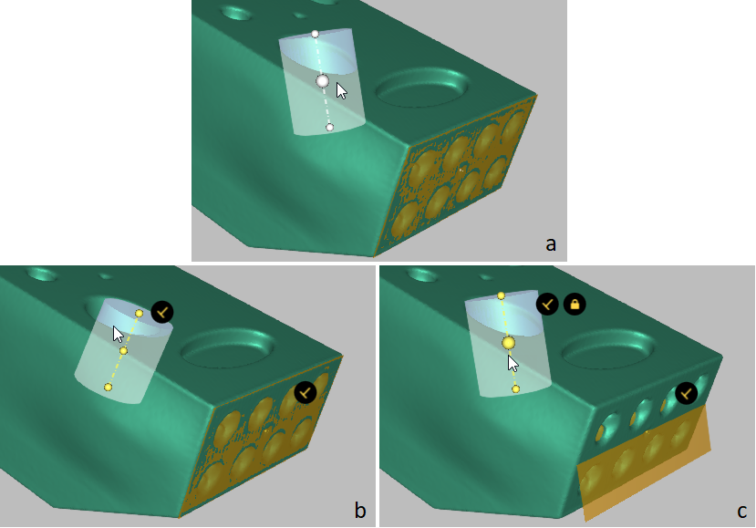
Figure 147 Example of ambiguous CAD primitive constraints.
Positioning CAD Primitives
The Precise positioning mode benefits from the presence of parametric data in the scene. Use the Precise mode to quickly and accurately position CAD primitives, and thus scans and models to which they belong.
In the Workspace panel, select the models and primitives you want to align.
Open Editor → Precise positioning.
In the Primitives box, select the CAD primitive you intend to position. Below the Primitives box you will see the available positioning options (see Table 16 for details), which appear as buttons and vary with the type of the selected primitive.
Note
Freeform and Autosurface CAD primitives are not available for precise positioning.
If some other objects belong to the parent group of the selected primitive and you want to apply the same positioning actions to them, check Apply to all objects in parent groups.
Click either of the self-explanatory positioning buttons. Artec Studio will position the primitive in accordance with the selected option and disable this button. You will see the alignment information in the Primitives box next to the name of the selected primitive.
Every positioning action is recorded in the local history, so you can undo or redo it:
To undo an action, use Edit → Undo or Ctrl+Z.
To redo an action, use Edit → Redo or Ctrl+Y.
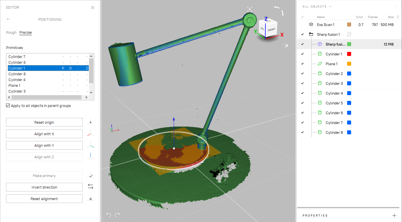
Figure 148 Editor → Precise positioning: the aligned CAD primitive is highlighted.
Button |
Purpose |
Status |
|---|---|---|
Move to origin |
Place the selected primitive’s point to the coordinate origin. For details, see Primitives’ Points To Use for Positioning. |
O |
Align with X/Y/Z |
Align the primitive with the respective axis. |
X, Y or Z |
Align with YOZ/XOZ/XOY |
Align the plane primitive with the respective coordinate plane. |
YOZ, XOZ or XOY |
Any |
CAD primitive that you first align with any coordinate axis or plane is considered primary. A primary object will be given a priority when conflicting alignments occur. |
P |
Make primary |
Make another object primary and remove this status from the current primary one |
|
Reset origin |
Undo the Move to origin action. |
|
Invert direction |
Invert direction of the axis or plane in the applied alignment |
I |
Reset alignment |
Reset all the positioning actions applied to the primitive |
Note
The Precise positioning tool does not affect objects with the Locked position status ( ). See Locking Object’s Reposition for details.
See also
Exporting CAD objects, Distance Maps and Sections and Volume.
Primitives’ Points To Use for Positioning
Depending on the type of a CAD primitive, you can use the following points in the Move to origin action.
Type of primitive |
Points for positioning |
|---|---|
Cylinder |
3 points: the center of the cylinder and the intersections of the cylinder axis with its bases |
Plane |
The center of the plane |
Sphere |
The center of the sphere |
Cone |
3 points: the cone vertex, the middle of the cone axis, and the intersection of the axis of the cone with its base |
Truncated cone |
3 points: the middle of the cone axis and the intersections of the axis of the cone with its bases |
Torus |
3 points: the center of the torus and the intersections of the axis of the torus with the sides of the box into which it is inscribed |
To select the center of a primitive for using in the Move to origin action, click the primitive or select it in the Primitives box. The selected point and the outline of the primitive will be highlighted in white (Figure 149, left).
When you hover the cursor over the primitive’s axis, other points for positioning will appear on it. To select any of the possible positioning points, click on it. The selected point will be highlighted in white (Figure 149, right).
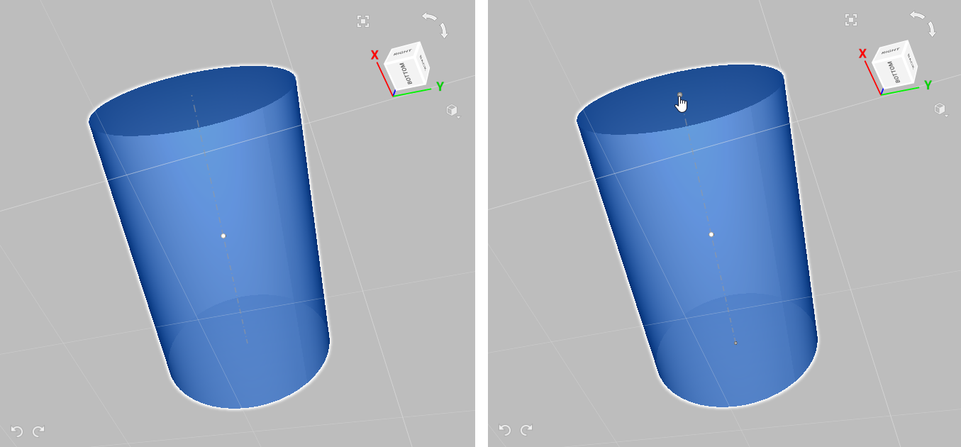
Figure 149 Selecting a point for positioning.
Editing meshes using CAD objects
In Artec Studio, you can not only generate 3D forms through 3D scanning, but also create complicated shapes through combining meshes, CAD primitives, and CAD models. The following tools for engineering tasks are currently available:
Boolean Operations
Starting from version 17, the basic set of Boolean operations is available in Artec Studio. You can create unifications and intersections between meshes and CAD objects, as well as subtract objects from each other.
The table below lists the available Boolean operations.
Icon |
Boolean operation |
This operation … |
|---|---|---|
|
Unification |
creates a new mesh by merging one or more objects with each other |
|
Subtraction |
creates a new mesh by subtracting one or more objects from another one |
|
Intersection |
creates a new mesh that is the common part of two or more source objects |
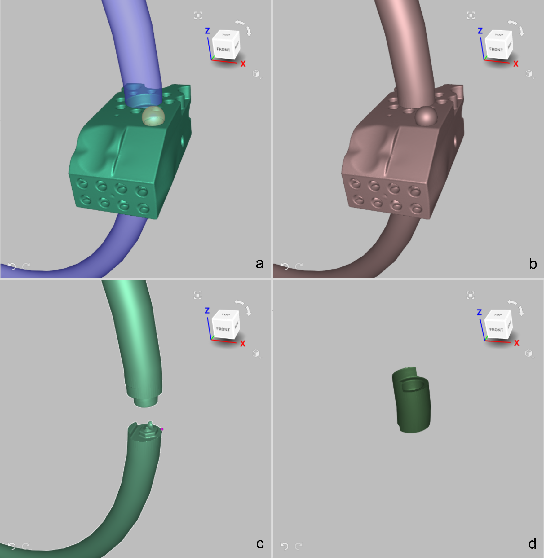
Figure 150 Examples of Boolean operations with objects: a—source objects, b—Boolean unification, c—Boolean subtraction, d—Boolean intersection
Boolean operations in Artec Studio can be applied to meshes, CAD primitives, imported CAD models and assemblies (collection of multiple objects). The following combinations are possible: mesh and mesh, mesh and CAD primitive, mesh and CAD model, mesh and assembly etc. The result of the operation is always a new mesh. The number of objects used in one operation is not limited, for example, you can create a Boolean unification by merging several objects.
Note
If you perform Boolean operations on a set of two CAD models, you will get a mesh as a result, not another CAD model.
To perform a Boolean operation, follow these steps:
Open the Construct panel and go to the Edit tab.
Click the icon of the desired Boolean operation.
Specify the objects for the operation.
For
 (Boolean unification):
Сlick Add object in the Objects to merge field.
Select one or more objects.
For
 (Boolean subtraction):
Click Add object in the Subtract from field.
Select an object.
Click Add object in the Objects to subtract field.
Select one or more objects. If only one object is selected in the Objects to subtract field, you can swap the objects selected for the operation by clicking the
 button.
For
 (Boolean intersection):
Click Add object in the Objects to intersect field.
Select one or more objects.
Note
To select an object, click it in the 3D View window or click its name in the Workspace panel. To deselect an object, click the x button to the right of its name in the Construct panel.
In order to preview the result of your boolean operation, enable the Preview toggle switch in the panel.
Note
The Preview option is currently available only for the Subtraction and Intersection operations.
If you need to keep the source objects intact, check the Keep initial objects option. Otherwise, they will disappear from the Workspace panel after the operation is completed.
Click the Create mesh button to confirm the operation. Artec Studio will create a Boolean unification (or Boolean subtraction, etc) mesh.
Splitting Mesh By Plane
You can split a mesh into segments using one or more pre-built planes. The result of split by each individual plane is two separate parts of the source mesh. The contact zone of these parts is sealed for both segments. The new parts appear as two separate meshes in the Workspace panel.
The split tool can be used in particular to precisely divide an object into manageable chunks for further 3D printing.
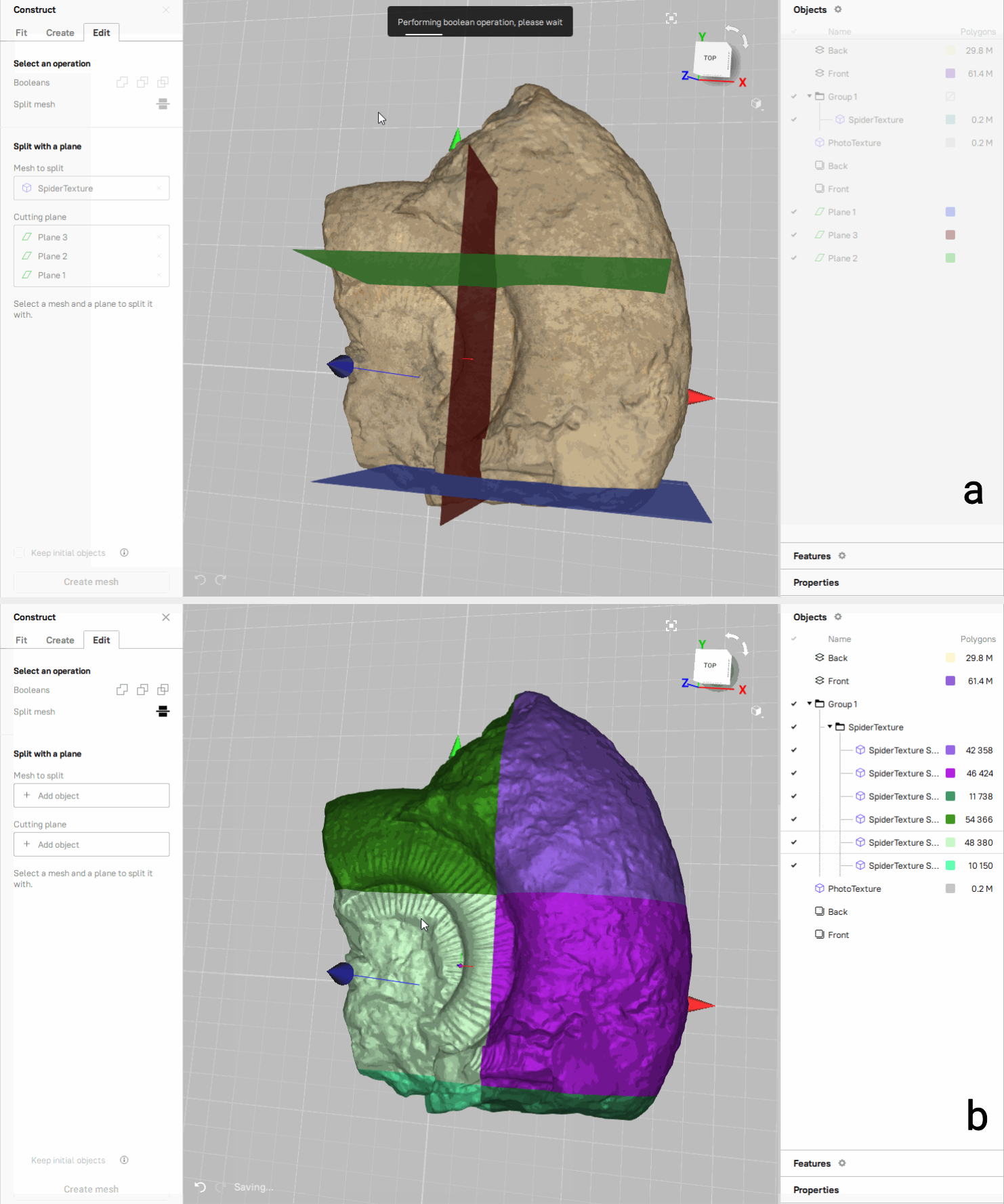
Figure 151 Example of splitting a mesh by 3 planes: a—before splitting, b—after splitting
To split a mesh by one or several planes, follow these steps:
Open the Construct panel and go to the Edit tab.
Click the Split mesh (
 ) icon.
Specify the objects for the operation:
Сlick Add object in the Mesh to split field.
Select a mesh that you want to split.
Click Add object in the Cutting plane field.
Select one or more planes.
Note
To select an object, click it in the 3D View window or click its name in the Workspace panel. To deselect an object, click the x button to the right of its name in the Construct panel.
If you need to keep the source objects intact, check the Keep initial objects option. Otherwise, they will disappear from the Workspace panel after the operation is completed.
Click the Create mesh button to confirm the operation. Artec Studio will split the mesh by the specified plane(s).
Working with Imported CAD Models
Imported CAD models can be aligned or compared with polygon models (fusion operation outputs).
Alignment
When aligning CAD models with polygon models, don’t use Nonrigid alignment and employ many point pairs (5–6 pairs). You can also align an imported CAD model with a mesh precisely by specifying datums.
For details, consult Datum Alignment, Manual Rigid Alignment with Points and Specifying Points and Editing Their Positions.