Scanner Calibration and Correction
The Calibration Tool is a special utility that enables you to calibrate Artec 3D scanners and correct an existing calibration. In general, calibration is the process of checking and adjusting a scanner’s measurements by comparing them with the standard (etalon) values. Every Artec scanner is delivered pre-calibrated.
In some cases, owing to careless handling or transportation (jolts, accidental drops or some other reason), the scanner may fail to capture surfaces properly. The scanned surfaces may only be partially reconstructed or may contain holes. You can resolve these issues by correcting or calibrating the scanner.
Depending on the scanner model, the Calibration Tool can operate in one of the two working modes:
Correction for Artec EVA scanner
Calibration of Artec Spider scanner
Suggestions for Use
Correction differs from calibration, in that it preserves the current calibration: it only changes the correction ratio so as to enable good reconstruction. Application of the correction does not guarantee that captured geometric shapes and linear measurements will be accurate. Use this procedure as a temporary measure until calibration is performed.
Mode |
Characteristics |
Speed |
For Spider |
For EVA |
|---|---|---|---|---|
Correction |
Inexact |
Fast |
No |
Yes |
Calibration |
Exact |
Prep required |
Yes |
No |
Important
Calibration is available for Artec Spider scanners only. Calibration of Artec EVA can only be carried out at the Artec production office.
Launching Calibration Tool
To launch the Calibration Tool, first ensure that the scanner you intend to calibrate appears in Artec Installation Center as either On loan or Activated. You can launch the tool either through the Start menu by clicking or in Artec Studio by selecting the Run Calibration Tool command from the File menu.
Connect the scanner. If you have several scanners connected, select the appropriate one from the dropdown list.
Note
The new Calibration Tool has the ability to detect USB types, and automatically make adjustments for compatibility. This makes it possible to connect scanners using USB 3.1 cables, without external adapters.
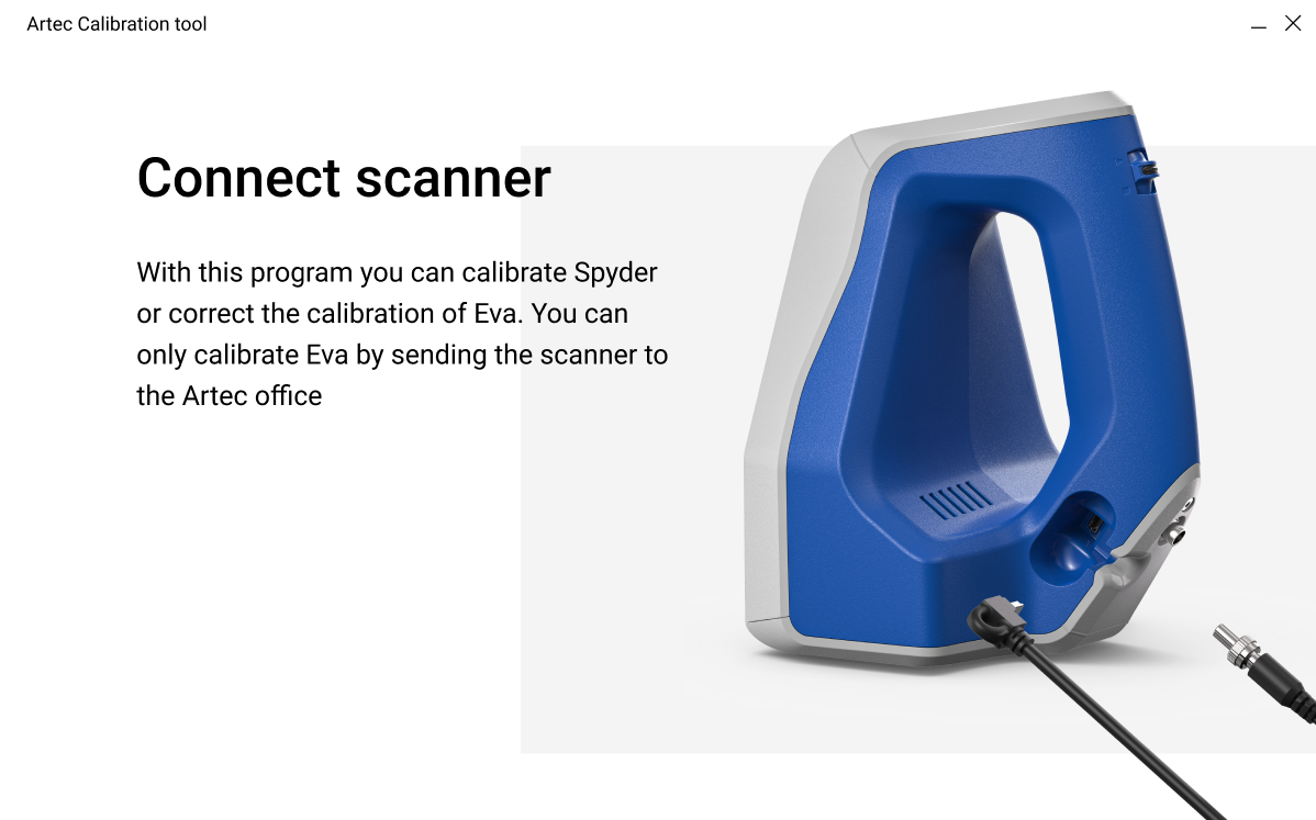
Figure 172 Calibration Tool window
Scanner Correction
Important
Apply correction sparingly, as a temporary measure until calibration is performed. If correction fails, please contact the Artec support.
Correcting Field of View for EVA
The Artec EVA scanner only allows you to correct their current calibration data on field of view.
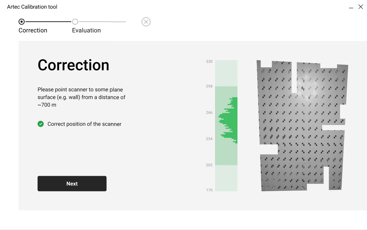
Figure 173 Artec EVA correction window
Launch the Calibration Tool as Launching Calibration Tool describes.
If multiple scanners are connected, select the scanner you want to correct. Otherwise, continue with the connected scanner.
On the main window, click on the Start button, and the scanner will start the preview.
Direct the scanner at the right angle to a flat, light (but not shiny) monochrome surface (e.g., a wall or floor) from a distance of 650–700 mm.
The Correction window will indicate whether the distance is optimal, and start rendering the surface.
Click Next, to perform the correction.
The Evaluation window, will then display the result of the correction. If the correction result meets your expectations, click on Save correction. Otherwise, click on Recorrect, and repeat the process.
Spider Calibration
To carry out the calibration, you will need the following additional equipment: a calibration rig, a scanner stand and a positioning sheet. Assembly instructions for the scanner stand and calibration rig are given in Assembling the Scanner Stand and Assembling the Calibration Rig, respectively.
Step 1: Set up Board
Unfold the positioning sheet and place it on a desk or any hard, planar surface.
Align the scanner stand with the rectangle marked on the sheet, paying close attention to the orientation of the slots in the stand cover (see Figure 174).
Place the scanner on the scanner stand, making sure that you insert the three scanner stems in the three slots of the stand cover (see Figure 175).
Set the calibration rig on the positioning sheet, turning its marker side towards the scanner as Figure 176 shows.
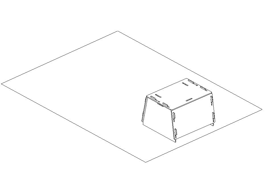
Figure 174 Scanner stand resting on the sheet.
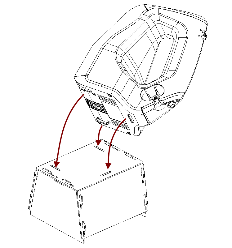
Figure 175 Placing Artec Spider on the stand

Figure 176 Calibration rig, positioning sheet and scanner stand with Artec Spider.
Now, launch the Calibration Tool as Launching Calibration Tool describes.
If there are multiple scanners connected, then select you scanner on the Calibration tool main window, and click on Start.
Enter the serial number of your calibration rig, and click Next.
Step 2: Warm up scanner
If the scanner temperature is outside the optimal range—for example, you just connected the device to a power outlet—the tool will notify you to warm the scanner up.
The warm-up time will depend on the actual temperature of the scanner. In any case, we advise against clicking Skip and instead recommend waiting for the Artec Spider to reach its optimal temperature.
Note
It is important to warm up the scanner to its optimal working temperature before carrying out calibration. For precise results, do not skip this step.
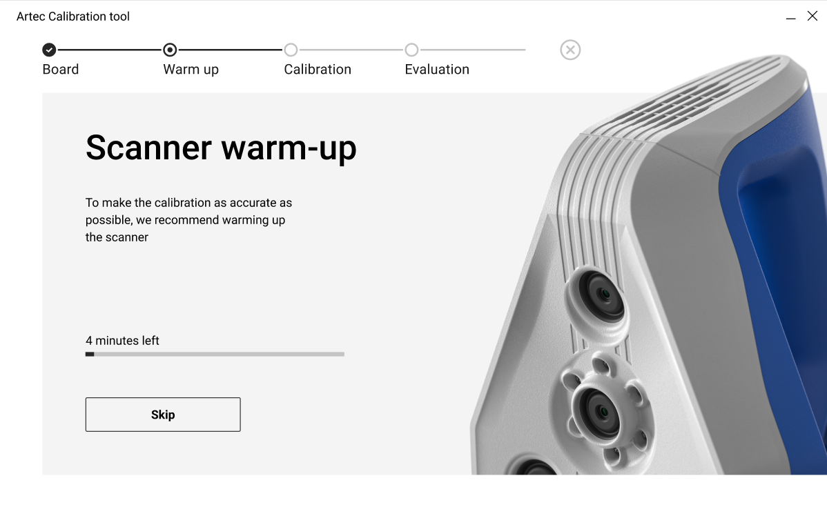
Figure 177 Warming up the scanner
Step 3: Calibration
After scanner reaches its optimal temperature, click Start to start calibrating Artec Spider.
Place the rig in its initial position such that the front edge of its base coincides with the color line numbered 1 on the sheet. As you do so, keep an eye on the Calibration window for the position plane to turn green plane. Once the plane turns green, stop moving the rig and wait for the scanner to capture the plane.
Wait for the tool to instruct you to move the rig to the next position on the pattern; the number for that position will appear on the screen. Move the rig and again wait for the scanner to capture the plane.
Repeat the preceding step for the remaining positions sequentially. Depending on the version of your calibration kit, the positioning sheet will have 11 to 15 positions.
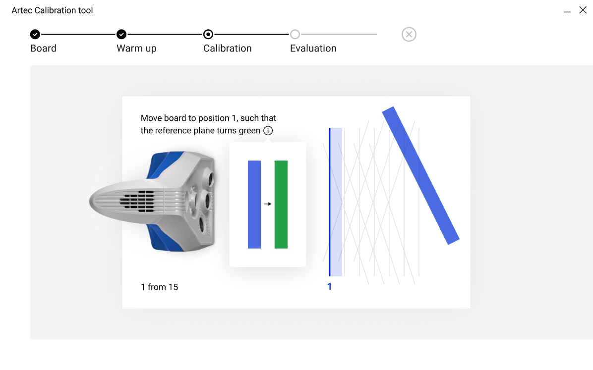
Figure 178 Moving calibration rig to position number 1
Step 4: Evaluation
Once you have captured the last position and the calculations have concluded, the Evaluation window will display the the quality of the calibration and accuracy.
If it indicates that the scanner is well calibrated, you can go ahead and click on Save Calibration .
Alternatively, direct the scanner at a flat, nonglossy surface (e.g., a piece of paper) from a distance of about 200 mm. Assess the quality of the reconstructed surface and check for any holes. If no holes appear on the surface and you are satisfied with the reconstruction results, go ahead and Save Calibration.
In case of discrepencies or dissatisfactory results, click on Recalibrate, and repeat the calibration process.
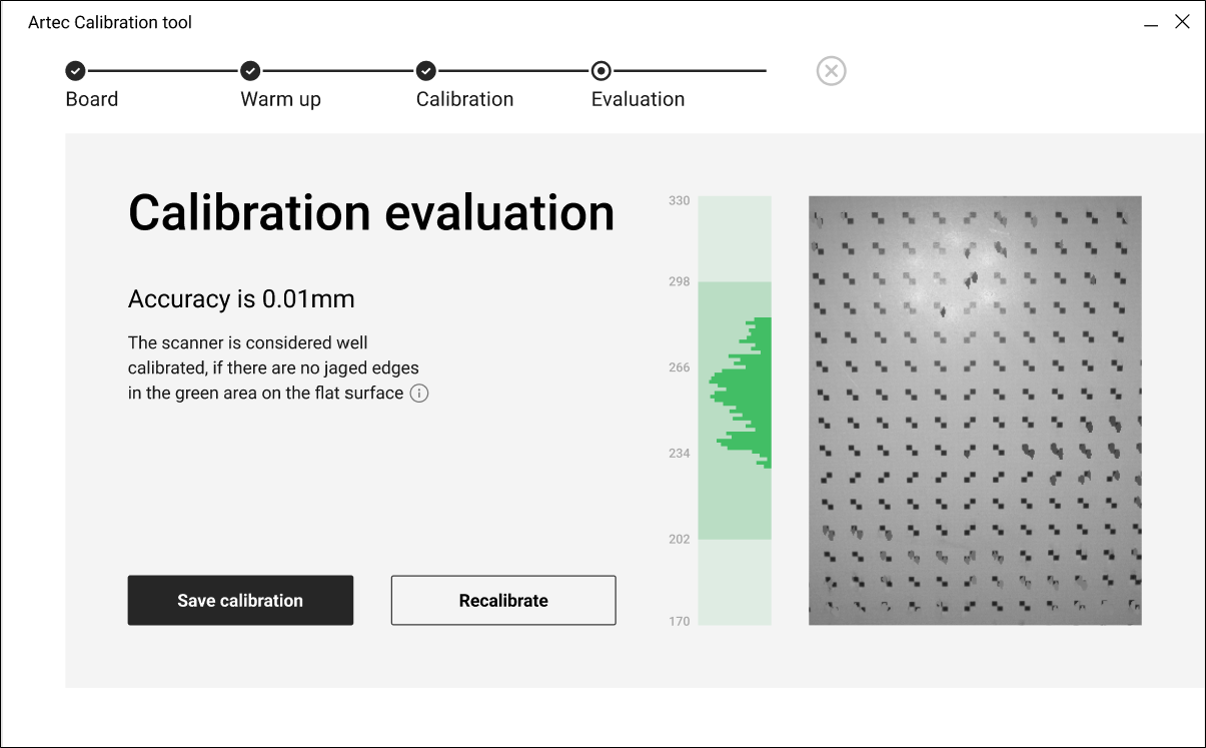
Figure 179 Evaluating calibration results
Notes Regarding Scanner-Calibration Files
Calibration and correction results reside in files that you can access as follows. Their location is
C:\Users\%name%\AppData\Roaming\Artec\Artec Installation Center
\Devices\SP.00.00000000.
Here, %name% is the current user folder and SP.00.00000000 is the folder corresponding to the scanner serial number. Note the following information regarding calibration and correction.
Once you apply correction results, the software will create an
ACDfile.Once you apply calibration results, the software will create
ACDandCORRfiles.All newly created files have names of the form
YYYYMMDD-HHMMSS, with the characters corresponding to the date and time of the file’s creation.Original
ADDandCORRfile names are based on the scanner serial number and have the formSP.00.00000000.
Note
You can restore the initial calibration by removing the ACD and CORR files whose names have the form 20131121_101010.
Note
If you use the scanner on several computers, you need not recalibrate it on every one. Simply copying the ACD and CORR files to the above-mentioned folder on each computer may be sufficient.
Assembling the Scanner Stand
The scanner stand comes unassembled with Artec Spider and consists of five parts (see Figure 180): two side walls, one front and one back wall (these parts are identical, however), and a cover. Before beginning assembly, lay them all out as Figure 180 shows. Then follow these steps:
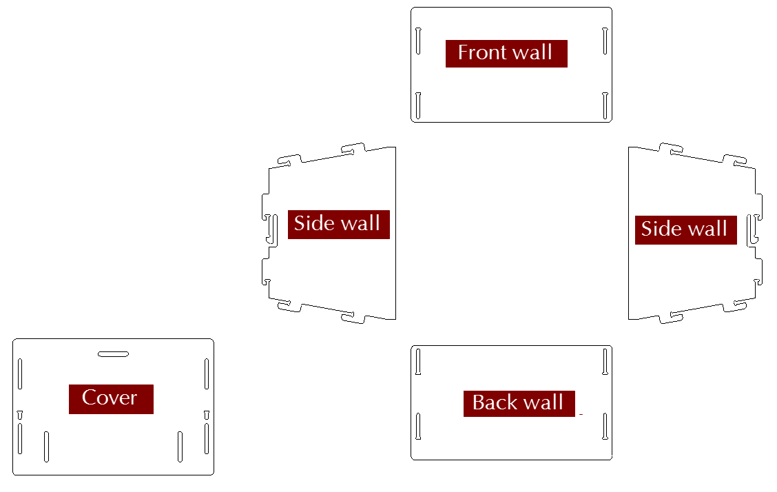
Figure 180 Parts of the scanner stand.
Raise the two side walls to the upright position, as Figure 181 shows. Noting carefully the orientation of the T-shaped slot, install the front wall to the side walls using the two pairs of hooks. Press the front wall and slide it down against the stop. Make sure the three walls are properly aligned with each other.
Install the back wall in the same way (see Figure 182).
Paying attention to orientation of the slots, install the cover using the upper hooks of the side walls (see Figure 183).
Press your thumbs against the T-shaped holes on the cover and shift it toward the back wall until you hear a click (see Figure 184).
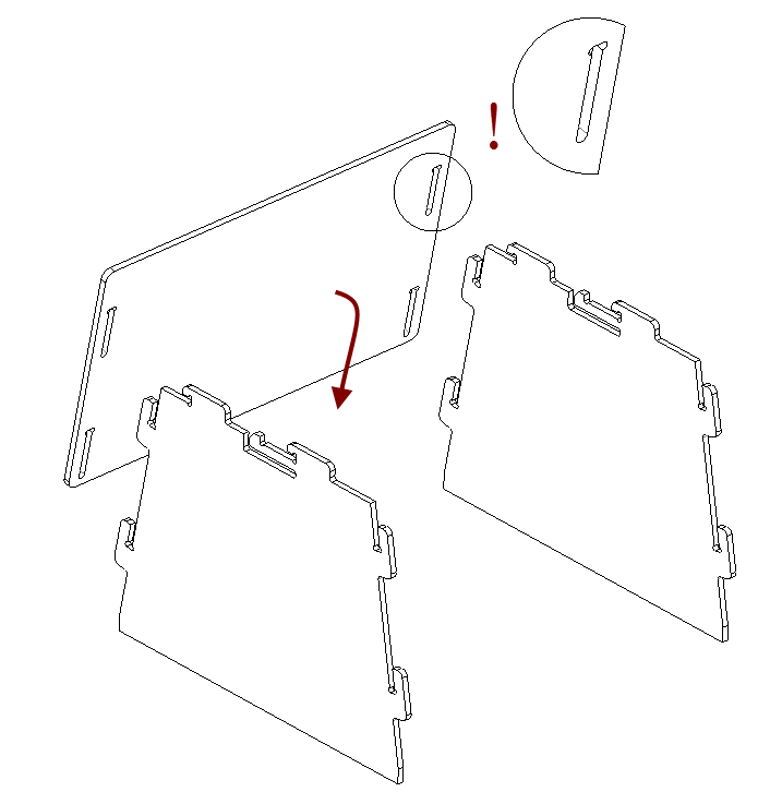
Figure 181 Assembling the front wall.
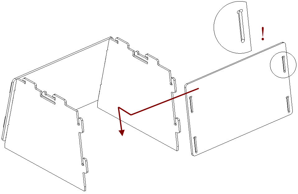
Figure 182 Assembling the back wall.
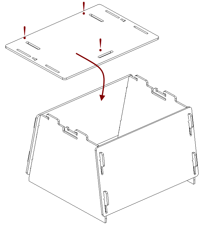
Figure 183 Mounting the cover.
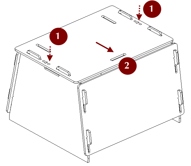
Figure 184 Latching the cover.
The scanner stand is now ready to use.
Note
To disassemble the stand, release the detents in the cover’s T-shaped slots (see Figure 180) using a thin object like a ballpoint pen. Repeat the assembly steps in reverse order (from Figure 184 to Figure 181), moving the parts in the opposite directions.
Assembling the Calibration Rig
The calibration rig comes only with Artec Spider and consists of the base and the board. To assemble the rig, follow these instructions:
Press the hinge of the base against your forefingers.
Unfold the bent leaves of the base, pressing on their edges with your thumbs.
Insert the board into the slot, as Figure 185 shows.
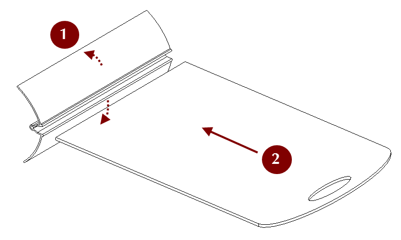
Figure 185 Assembling the rig.