Scanning with Micro II
Open Micro II Scan Panel
Launch Artec Studio.
Open Scan panel.
Click Scan with Artec Micro II and wait for Micro II to initialize.
Note
A checkerboard light pattern will appear on the scanning space, and the swivel bracket with the fixture starts rotating.

Figure 7 Scan panel with Micro II initialising.
Calibrate Scanner
When launching Micro II for the first time, you will need to calibrate your scanner.
To calibrate Micro II:
Open Artec Studio
Install the calibration plate on the fixture as it is shown in the image below or in the Scan panel of Artec Studio.
Note
The installation place has magnets, so the fixture can be easily removed.
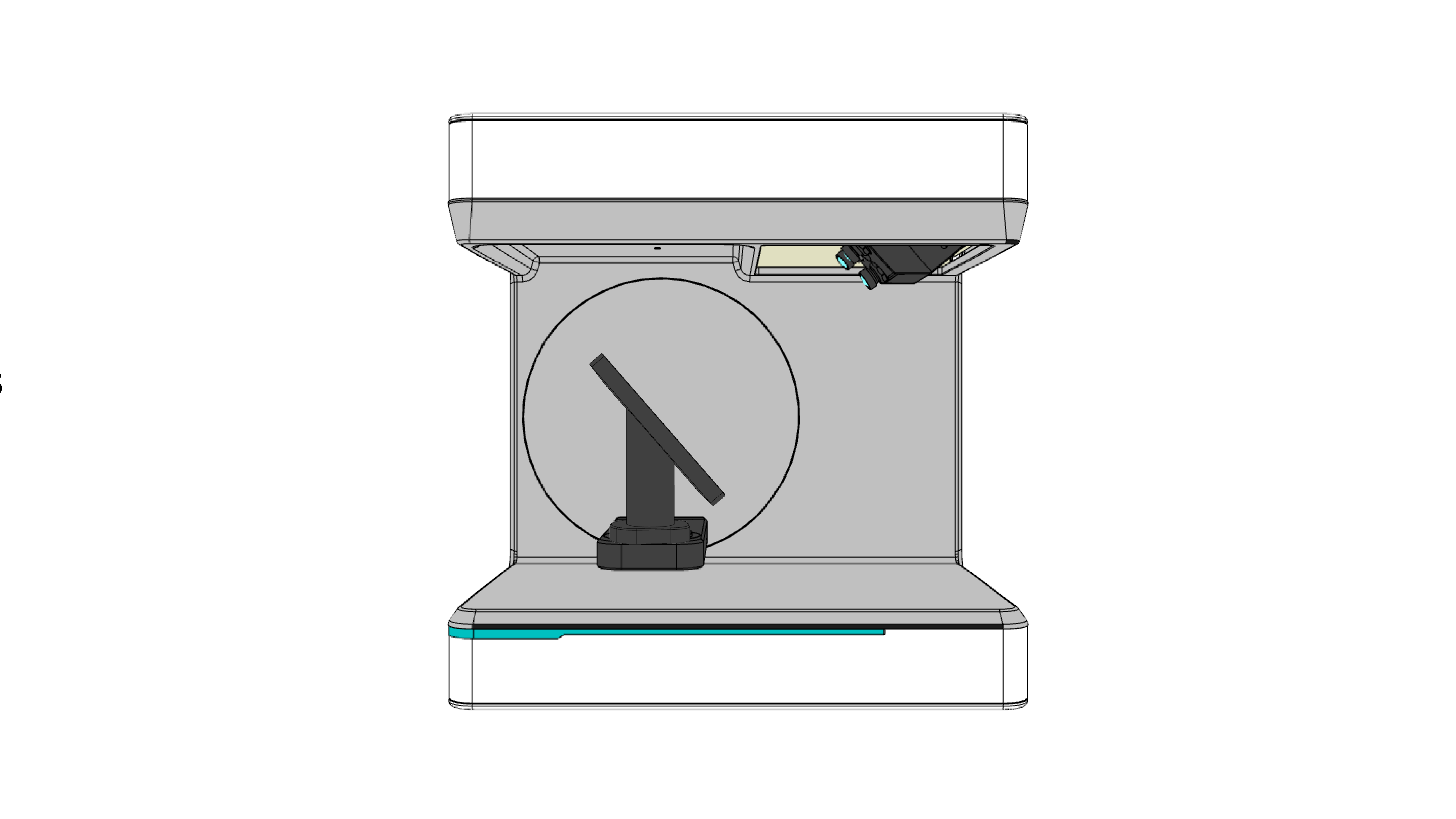
Figure 8 Calibration plate fixation.
Once the calibration plate is fixed, select Load the calibration dataset from a calibration plate option
Click the Calibrate button. Calibration will automatically start.
When Artec Studio completes calibration process, Micro II is ready for scanning.
In case of any problems with calibration plate data and failed calibration, you will see the instructions on the Scan panel.

Figure 9 Failed calibration.
Please contact Artec 3D Support to get the calibration file.
Prepare Objects
You can affix an object using either of the holders mentioned here. The maximum object dimensions are 200x200x150 mm.
Difficult-to-scan objects with black, transparent and reflective surfaces will be badly reconstructed during scanning. You can use anti-glare spray but the most preferrable option for small objects is talc powder. For the best distribution of powder particles, it is recommended to use Air Brush.
Warning
To prevent damage to the cameras, refrain from spraying talc on the object while it is on the Micro II table. Instead, spray the object outside Micro II and then place it on the table afterward.
Perform Scan
To make a scan, perform the steps:

|
The object must be entirely visible. For separating the object from the holder, please refer to Cutoff height and Bounding cylinder radius sections. |
|
Tune it to minimize areas highlighted in red (potentially noisy areas). |
|
For simple cases, use Preview. If your computer has an Nvidia graphics card, opt for Automatic path. |
|
Micro will start capturing frame while swinging the fixture platform and rotating the swivel bracket. |
|
Use the left-mouse button to rotate and the scroll wheel to zoom. |
|
Orient object in 3D view and then click this button. |
If necessary, flip the object and affix it again. Then repeat the steps above to scan the remaining areas. You’ll need to later align the scans obtained this way.
Framing and Quality Options
The Micro II camera provides a real-time preview (see the image above, ➊). Use the image from the camera to orient the object correctly. Ensure the following:
Preview area fits the entire object.
The cross mark appears in the middle of the object.
Use the following options to improve the quality of the resulting 3D model and to capture the texture of the object:
Brightness |
Brightness is the scanner’s reconstruction capability. First, increase it to make the object visible in the preview. Next, tune it to minimize areas highlighted in red (potentially noisy areas). |
Mode |
Defines the scanning mode, selecting the most suitable option based on your requirements - either deep and broad scanning with high-quality reconstruction or scanning with maximum accuracy. The latter is recommended for metrological measurements. |
Move scans to the origin |
Positions the scans in the coordinate origin. The possible drawback is that the scans might be slightly misaligned. |
Use GPU |
Determines whether the CPU or GPU resources are used during scanning. In most cases, GPU is the preferred option, as it enhances the quality of resulting scans. |
Bounding Cylinder
To specify the scanning area, you can adjust the value of the Bounding Cylinder radius. By default, this value is equal to 100 mm. It means that the resulting scan will encompass only points within this cylinder, with a radius of 100 mm. The rest points will be excluded from the output data during reconstruction.
To familiarize yourself with the concept of bounding cylinder, please refer to the image.
Cutoff height
By adjusting the Cutoff height value, you can determine the height of the area to be excluded. When Cutoff height is set to 50 mm, it signifies that all data from the bottom of the bounding cylinder up to a height of 50 mm will be omitted from the output data.
For better understanding, please refer to the image.

Figure 10 Bounding cylinder with cutoff height - default values.
Automatic Scanning
Micro can create a path automatically by analyzing the affixed object and ensuring sufficient surface coverage with a minimum of frames.
Note
To start Automatic path, your computer needs to have an Nvidia graphics card with at least 2 GB of memory and a CUDA compute capability of at least 3.5.
Adjust Brightness as necessary.
Select the Automatic path from the Scanning path dropdown list.
Wait for the scanner to finish capturing. It usually captures 80 frames.
Examine the scan and add one frame as necessary.
Flip the object, affix it, select the Auto-align new scans with those marked in Workspace checkbox and repeat these steps again.
Auto-Alignment
When creating each new scan using the Automatic path, you can benefit from the auto-alignment.
Ensure the previously made scans are selected in Workspace.
Once enough data has been scanned, the Auto-align new scans with those marked in Workspace checkbox will become active and checked.
Scanning Paths
Scanning path is a set of turntable positions relative to the camera due to the scanner’s rotary mechanisms.

Figure 11 Fixture platform and swivel bracket’s rotation.
There are two main parameters that affect the number of these positions and the number of frames:
Object’s size
Geometry complexity
Default Paths
Artec Studio provides the set of the predefined scanning paths. Click the Scanning path drop-down list and select a suitable item from the Default paths nested list.

Figure 12 Default scanning paths.
The tables below provide a description of the default paths.
Size- and complexity-based paths |
|
|---|---|
Small → Simple |
An object no bigger than 5 cm with no difficult-to-reach areas and few or no geometrical irregularities |
Small → Complex |
An object no bigger than 5 cm with many difficult-to-reach areas and numerous geometrical irregularities |
Large → Simple |
An object that’s at least 5 cm with no difficult-to-reach areas and few or no geometrical irregularities |
Large → Complex |
An object that’s at least 5 cm with many difficult-to-reach areas and numerous geometrical irregularities |
Preview |
A quick preview from six different angles. Use to check how well the object surface can be scanned or how many scanning angles it requires. |
Single frame |
Capture just one frame without rotating the turntable. Use this mode to cover blind spots from other trajectories—simply rotate the object to face the camera. |
Rotation only |
Objects that are ring-shaped or that can’t be properly affixed to the turntable can fall off when the arm swings. This path instructs Micro to rotate the turntable only, without tilting the arm (see Figure 11). |
Adding One Frame
After scanning an object, you may need to add separate frames from certain angles to fill in unscanned areas.
To add a frame into the existing Micro scan captured using either of the paths, follow the steps:
In the 3D view window, orient the object in the way the unscanned area is facing your view direction.
Click Add one frame.
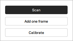
Figure 13 Adding one frame.
If the current scan orientation doesn’t allow adding a frame, this button will be grayed out. To resolve this issue, try reorienting the scan in the 3D view window.
Creating New Path
You can create a custom scanning path if the default paths aren’t optimal for the object. For this purpose, the Scanning path drop-down list contains the Add new path item.
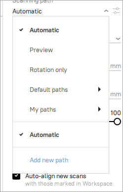
Figure 14 Add new path.
After selecting Add new path, the path editor will open.
By clicking to the right of the step row, via the pop-up menu you can delete, duplicate steps, and create a path sequence.
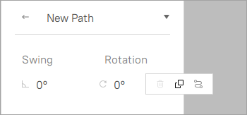
Figure 15 Creating new path.
Each step defines a position of the turntable relative to the Micro cameras using two parameters:
Swing defines an angle of the turntable tilt. The value is in range of -180° to 90°. The default value is 0°, which means there will be no tilt of the turntable.
Rotation defines a rotation angle of the turntable (clockwise). The value is in range of -180° to 180°. The default value is 0°, which means that the turntable will not rotate.
Thus, by setting rotation angles in each tilt position, you create a new scanning path.
Creating Path Manually
Adding a new path manually is reduced to a combination of the following operations:
Filling in the parameters of a certain step.
Duplication of the step and editing of the created one.
Removing unnecessary steps.
All these operations are performed using the pop-up menu described above.
After you have created the necessary steps, click Save. Your path will now be available in the Scanning path → My paths list.
Creating a Path Sequence
Artec Studio provides the ability to automatically generate a scanning path by setting only key parameters of a path sequence.
Click Add new path in the Scanning path drop-down list. Then, click to the right of the step row and select Create sequence from a pop-up menu.
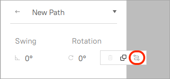
Figure 16 Creating the sequence.
The following parameters must be set to generate the path sequence:
Swing start angle is the largest inward tilt of the turntable.
Swing end angle is the largest outward tilt of the turntable.
Swing interval controls the amount of the tilt positions.
Rotation interval controls how many turns the turntable will make in each tilt position.
Once all parameters have been set, Artec Studio will automatically count how many positions and frames the sequence will create.
Caution
If you set the intervals too short, Artec Studio will inform you that the frame count is exceeded (see figure below).
Click the Generate button to get back to the path editing menu with the generated path.

Figure 17 Generating the sequence.
If the automatically generated path sequence satisfies you, click Save and now your custom path will be available through the Scanning path → My paths nested list.
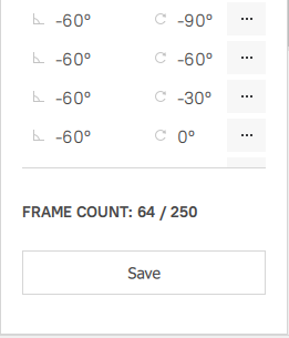
Figure 18 Save the sequence.
Note
It is possible to add a subsequence to an existing sequence, for example with the specific rotation interval for a certain tilt position. Select the desired step in the sequence, click to the right of the step row and select “Create sequence”. Perform the same operations to create the sequence as described above.
Any step from the sequence can be edited manually, which allows to create a perfect scanning path for a specific object.
Editing Paths
Each custom path can be edited via button ![]() .
.
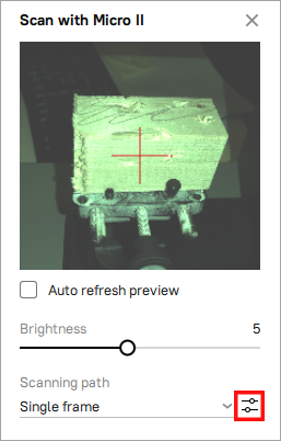
Figure 19 The edit ![]() button.
button.
Next, you can do any available operations on the paths as described above. Also note the drop-down list at the top right of the path editor, which allows you to save, duplicate, rename and delete the path.
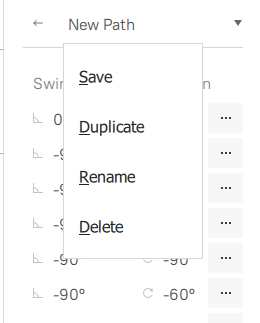
Figure 20 Operations with the path.
You can also use button ![]() with the default paths. You can’t edit them directly, but you can create your custom paths based on them. Use the Duplicate item in the drop-down list as shown below:
with the default paths. You can’t edit them directly, but you can create your custom paths based on them. Use the Duplicate item in the drop-down list as shown below:
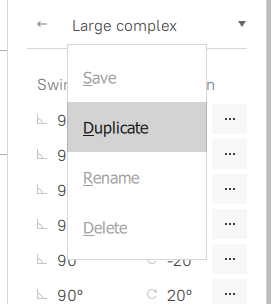
Figure 21 Duplicating the default (Large normal) path.
Angles
Object holders may often obstruct an object and prevent the scanning.
The object on the photo below is obstructed and will not be scanned from this angle (note the object’s shadow).

Figure 22 The obstructed object.
Regardless of the object type and the way it was attached to the turntable, the bottom part will always be inaccessible to Micro II, so, if you need the object to be fully scanned, flip the object and make a second scan after the first one.
Depending on the object’s complexity, some objects may need more than two scans to be compete.