How It Works
Principle
Ray utilizes a LIDAR method to measure distance to a target object by emitting a pulsed laser light and then measuring the reflected beams. Differences in laser wavelength allow to calculate distance and obtain a digital representation of the object. When scanning, Artec Ray makes two types of movements: the body rotates around the stationery base platform and the mirror rotates around its axis (Figure 1).
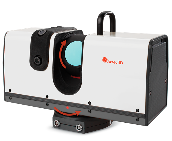
Figure 1 Ray scanner movements.
Point Cloud
The digital representation of the object scanned using Ray is called a point cloud, or point-cloud scan. Artec Studio builds a polygonal mesh from this data and shows a simplified copy of it.
Point Density
Ray internally controls scan resolution in angular terms, i.e. number of beams per degree. Since the scanner performs two types of movements, we define horizontal and vertical planes with measures per degree:

Points per degree |
Horizontal (blue) |
Lines per degree |
Vertical (red) |
The more the beams fit in one degree, the better the resolution. A certain number of beams, however, produces different point distribution at different distances. The farther the surface from Ray mirror, the larger the distance between points (see red segments in Figure 2). Large distance between points assumes the small point density value. So, it is more practical to operate a linear value of point density measured in millimeters between beams on a particular distance (Between points and From Ray, respectively Adjust Point Density).

Figure 2 Understanding point density.
For simplicity, horizontal and vertical point density are set equal in Artec Studio. Application features the Point density slider designed to control the number of beams, and therefore point distribution in both planes simultaneously.