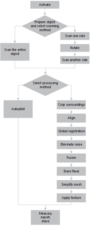
3D Scanning at a Glance
Before you start using the guide, we want to show you how easy 3D scanning can be. Although this well-structured manual covers all the matters related to Artec scanners and software, you may find it helpful to have an overview at your fingertips. This brief summary will assist you in getting started right away! But if you prefer to begin with comprehensive and detailed information, you can skip this chapter.
Activate
The scanner case includes everything you need to start 3D scanning, except a computer. At a minimum, your PC must run the 64-bit version of Microsoft Windows 7 or 8 (10 is also supported). The more powerful the PC, the better. The main memory (RAM) and graphics card are the most critical components (visit our FAQ page for more information).
Warning
Don’t connect the scanner just yet! Continue reading for more information.
- Register for an account at my.artec3d
- Sign in and download Artec Installation Center from the welcome page
- Install Artec Installation Center. When prompted, enter your email and password.
- Plug the scanner into a power outlet, then connect it to your PC using the USB cable
- Wait for Windows to detect the scanner. Click Activate.
- Click Install in the Software section to get Artec Studio running on your machine
(For more details, see User Account, Scanner Activation and Offline Activation.)
Prepare
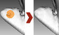
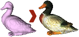
Most objects are easily scannable. Before scanning transparent, reflective or black objects, we suggest applying a powder coating or a special anti-glare spray.
To scan monochrome objects with simple geometric shapes, do the following:
- Add auxiliary objects (e.g., crumpled paper) to the scene
- Paint markers (e.g., “X” shapes) on the surrounding surfaces
Be sure to provide good ambient light. (For more info, see Selecting and Preparing Objects for Scanning.)
Scan

Launch Artec Studio, then aim the scanner at the object.
Hit the
F7key or press on the scanner to start Preview mode.
- Geometry + Texture is the default scanning mode and is suitable for most cases
- For older PCs, Geometry mode is a good alternative
- The Real-time fusion mode creates a model in real time, allowing you to skip postprocessing; click Stop, then select the Real-time fusion checkbox and click Preview.
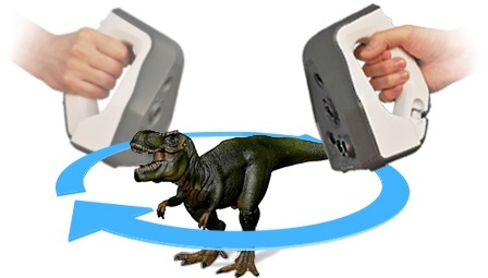
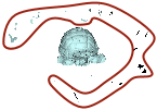
Make sure the object is visible, then press
once again to initiate recording. If possible, scan all sides of the object in one go, slowly moving the scanner around it as pictured below.Note
While scanning, pay closer attention to the object on the screen than to the actual object.
If you hear an alert sound and the screen displays an error against a red background, smoothly aim the scanner at the area you just captured. Possible reasons for the “Tracking lost” error include the following:
- You are scanning simple geometric shapes
- The part of the object you are scanning is too small
- Scanner movement is too fast
Press
 to display the scan in the Workspace panel.
Turn and Scan (Optional)
Note
This part is optional.
Turn the object and capture any remaining unscanned regions (press ). Also, to facilitate alignment, record at least one previously scanned region.
(For more info, see Artec Scanners: Buttons and LED Indicators, Tweaking Scanning Options, Scanning Procedure, Tracking Modes, and Scanning With Real-Time Fusion.)
Autopilot

For beginners, the easiest way to obtain a 3D model is by using Autopilot. It’s also a great time saver for advanced users. If you prefer performing all the steps manually, refer to the Process Manually section.
Autopilot is a special mode that helps users obtain a complete 3D model without learning all the ins and outs of postprocessing. It consists of two major parts: semiautomatic (editing and alignment) and automatic [1].
To produce a model,
Click Autopilot in the left panel or hit
F9.Become familiar with the steps that you will perform in this guided mode (listed in the welcome screen).
In the Workspace panel, use the
 flag to mark all scans that you intend to use, then click Next.
Then specify the input parameters for the model-creation step and click Next. Primary settings may include the following:
Note
We suggest consulting the tool tips, which you can reveal by clicking the
 button next to the option name.
- Scan quality (geometry). Click to determine whether your scan of the object has the correct geometry by examining the tool-tip images.
- Scan quality (texture). Click , look at the images and decide whether your scan has sufficient texture.
- Hard-to-scan surfaces. Select the checkbox if your object has surfaces that are difficult to capture. Consult the image samples by clicking the button.
- Decide on the Object size by referring to the image samples.
- Leave the default values for the remaining options in this window (sufficient for most cases). For advanced scenarios, you can tweak these settings (more details appear in the sidebar).
- Scan quality (geometry). Click
If necessary, erase any extraneous objects that can hinder postprocessing. Learn how to use Eraser by consulting the Erasing Portions of Scans section.
Once you’re done, click Next. If the object was captured over several scans, Autopilot will align them and show you the result. You can approve it or align the scans manually (consult Manual Rigid Alignment Without Specifying Points).
Click Next.
Autopilot will begin postprocessing [1]. Once it’s finished, a message will appear informing you that the model is ready. Click OK.
| [1] | (1, 2) Automatic steps may include the following:
|
Process Manually
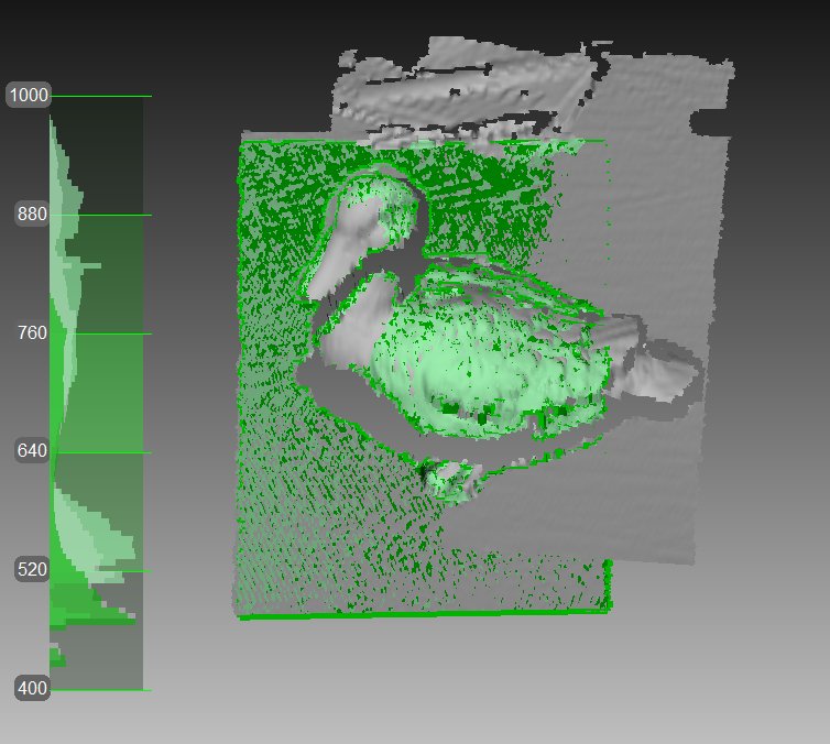
Crop Surroundings

Once you finish, click File and select Save project. Close the Scan panel; preliminary registration will start automatically. You can then crop the surroundings.
Purpose: To erase auxiliary surfaces (e.g., a table or floor).

Steps: Open Editor → Eraser → Cutoff-plane selection. Follow the instructions.
(For more info, see Editing Scans.)
Align

Purpose: To align several scans. Skip this step if only one scan is in the Workspace panel.
Steps:
- Mark two or more scans using , click Align and select those scans in the Rigid tab while holding the
Ctrlkey. - Click Auto-alignment.
- If alignment fails owing a lack of texture or lack of overlapping areas, manually match the features among the scans and click the Align button.
(For more info, see Scan Alignment.)
Global Registration

Purpose: To simultaneously optimize the frame position across all scans, thus preparing them for further processing.
Steps: Mark scans using , then click Tools → Global registration → Apply.
(For more info, see Global Registration.)
Eliminate Noise
Purpose: To erase large outliers and some noise.
Steps: Open Tools → Outlier removal → Apply.
(For more info, see Editing Scans and Outlier Removal.)
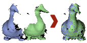
Fusion
Purpose: To create a model (a single surface, as opposed to the multiple surfaces that constitute the source scan).

Steps: Select Tools → Smooth fusion → Watertight → Apply.
To obtain sharper surfaces, select Sharp fusion. In both cases, resolution can be adjusted: the smaller the value, the more precise the resulting surface.
(For more info, see Fusion.)
Erase Flaws (Optional)
Purpose: To erase any outliers and poorly scanned regions.
Steps: Click Editor → Defeature brush. Follow the instructions.
(For more info, see Editing Scans.)
Simplify Mesh
Purpose: To reduce the file size by decreasing the number of polygons without significantly distorting the actual 3D geometry.

Steps: Click Tools → Mesh simplification → Apply.
(For more info, see Mesh Simplification.)

Measure, Export, Share


Export the model: open File → Export mesh. Select the required format, specify the folder and file name, then click OK.
Measure the model: open Measures, then select one of the following:
- Linear for distance calculation (points are connected by lines)
- Geodesic for distance calculation (points are connected by curves that pass over the model surface)
- Sections for area and volume calculation
Share the model on viewshape.com by opening the Publish toolbar
(For more info, see Exporting Models and Scans, Publishing to the Web and Measurement Tools.)
Tips and Tricks
- You can reset all settings to their defaults using
F10→ Scan tab → Reset to defaults - To return any altered parameters in the Tools panel to their default values, click the adjacent
 button. The
  button indicates a default value.
 - Save screenshots by hitting
Ctrl+Shift+S - Apply annotations using Measures → Annotations, enter the tag label and type text, then click Apply.