Scanning
Scanner Buttons and Capture Modes
Your 3D scanner may be in one of the following capture modes (each of which has a corresponding color and flicker rate of the LED indicator on the device if you’re using an Artec scanner):
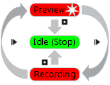
Figure 43 Understanding capture modes (colors correspond to scanner LED indicator colors).
- Idle—the LED is steady green
 .
. - This mode indicates either that the application has detected the scanner or that the user has clicked the Stop button in the Scan panel or pressed the
 button on the scanner body (see Figure 12). In this case, the 3D scanner is not flashing.
 - Preview—the LED is flashing red
 .
. In this mode, the 3D scanner is capturing images, but the software is neither performing alignment nor recording captured frames. To start this process, either click the Preview button in the Scan panel (see Figure 55), press the
 button on the scanner body or hit the
 F7key on the keyboard. This mode is useful when doing the following:- Checking the 3D scanner’s field of view
- Determining the best position for the object
- Preparing to recording and developing a scan procedure
- Adjusting texture brightness
- Recording—the LED is steady red

- Scanning takes place in this mode, with the software storing 3D data to disk or RAM. Activate this mode either by clicking the Record button in the Scan panel, hitting the
Spacekey on the keyboard or pressing the button (do so once for Preview and a second time for Recording). To pause recording, either click Pause in the Scan panel, press on the scanner body or hit the Spacekey.
Selecting and Preparing Objects for Scanning
Artec 3D scanners employ the structured-light method of 3D reconstruction. Since they capture 3D frames using optical technology, some types of objects are difficult to scan. Certain techniques, however, enable successful scanning of such objects. For example, you can cover a transparent or dark object with a light paint or dust it with talcum powder. You can also use other easily removable substances or a special anti-glare spray.
| Surface Features | Possible Solutions |
|---|---|
| Black or very dark | Dust with anti-glare spray |
| Shiny or reflective objects | Dust with anti-glare spray, tilt scanner when capturing |
| Transparent (glass, certain kinds of plastic, etc.) | Dust with anti-glare spray |
| Thin edges | Add background geometry (e.g., crumpled paper) |
Technique
Artec 3D scanners capture objects at a rate of 15 frames per second to ensure that adjacent frame areas overlap as you gradually move the scanner. Artec Studio uses features in overlapping areas to automatically align captured frames. It performs this task in real time, providing immediate access to the frames in a single coordinate system. You can evaluate the captured area after the scanning session to determine which parts of the object require additional scanning.
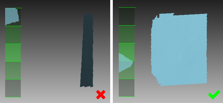
Figure 44 Scanner orientation and reconstructed surfaces.
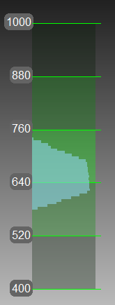
Figure 45 Distance meter in 3D View window showing surfaces that fall within the optimal range for Artec EVA.
To accurately capture an object or scene, follow these steps:
Pay closer attention to the object on the screen rather than looking at the actual object.
Ensure that Artec Studio can accurately register frames from the scanner. To this end, do the following:
- Don’t move the scanner too fast
- Keep the object as close to the center of the field of view as possible
- Maintain the scanner orientation in such a way that the field of view is sufficiently filled with surfaces (see Figure 44)
- Try to position the scanner as close as possible to the center of the range meter [1] or a little below it (closer to the object; see Figure 45)
If you’re capturing an object over several scans, remember to capture a common area in each one to ensure successful alignment
If you’re capturing an object in one scan, do so all the way around the object—regardless of direction—plus a little more (360+ degrees)
Avoid capturing any objects that may change shape during the scanning process. When the geometry of the scene is changing, the system may fail to find the correct position of new frames relative to previously aligned ones. If you have captured unwanted objects, you must remove them later during the editing stage (see Editing Scans).
Don’t record too many frames: ensure that you have sufficiently scanned all regions, but avoid scanning them twice, except when providing overlapping areas for subsequent alignment.
| [1] | Technically, the center of the range meter is the center of the depth of view. The 3D scanner has near and far cutting planes (see Figure 11) that determine the optimum distance between the scanner and the target object. Artec Studio offers the Range meter feature so you can easily visualize the distance between the scanner and the object during the recording process. The Range meter comprises a set of semitransparent diagrams located on the left side of the 3D View window (see Figure 45). Each histogram displays the distribution of captured surface points by distance from the scanner. The color corresponds to the set of surfaces from which it was obtained: by default, gray indicates registered key frames, light green indicates the last few frames of a registered sequence, dark green indicates the last successfully registered frame and red indicates a registration error. |
Scanning Procedure
- Artec Studio creates a new scan in the Workspace panel at the beginning of each session.
- When you start Preview mode, Artec Studio will hide all uploaded scans. This mode helps you to determine how well the 3D scanner sees the object, and it helps you to identify areas that may cause trouble during the scanning session. To begin the scanning process, click the Record button in the Scan panel or press the button on the device body.
- If your 3D scanner is equipped with a texture camera, Artec Studio will activate the scanner’s texture flash and capture color images that it will later use to texture the 3D model.
Prepare the object and make sure it has enough geometry and texture details (see Selecting and Preparing Objects for Scanning).
Provide even lighting without using direct sunlight.
If you have connected just one 3D scanner to the computer, Artec Studio will select it automatically; otherwise, you must select the appropriate device from the dropdown list under the Advanced section of the Scan panel.
Create a new project before getting started: use the
 button in the Workspace panel, select from the menu, or use the shortcut
 Ctrl + N. Once you have saved the project, you will be able to load or unload the scans as necessary and thereby limit RAM usage (see Project Operations for details).Decide how many sessions you need in order to capture the entire object. By using a special third-party rotating table, you may be able to avoid interrupting the session and eliminate the need to turn the object by hand. Depending on your choice, you may
- Turn the object
- Position yourself to gain access to the other area
- Use a rotating table
Click Preview or press
on the scanner. Direct the scanner at the object and practice your movements around the object, taking into account the proper Technique.Note
If you wish to use the Enable automatic base removal option, first direct the scanner at the surface that supports the object.
Click Record to start capturing.
Gradually move the scanner while monitoring the process in the 3D View window
Capture what you can and pause or cease recording by clicking the Pause or Stop button, respectively. Choose Stop if you must make adjustments to the object’s positioning (see the next step).
Turn the object or otherwise adjust it as necessary, then capture any remaining unscanned regions.
Once you have successfully captured the object from all sides, click the Stop button or press
on the scanner body.
Tracking Modes
The software provides three tracking modes and one option:
- Geometry + Texture, or hybrid
- The optimal (and default) algorithm for 3D scanners equipped with a texture camera. It uses features from images obtained using the texture camera as well as geometrical features of the object and thus is more likely to successfully capture flat or textureless objects. The only possible drawback is greater CPU utilization compared with other algorithms, potentially decreasing the frame rate for less powerful computers. You can use this mode with Artec MHT, Artec EVA, Artec Spider and third-party 3D scanners.
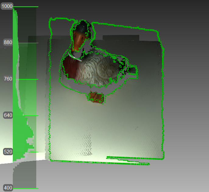
Figure 46 Texture tracking renders color object (scanner’s current field of view outlined in green).
- Geometry
- The default algorithm for all 3D scanners that lack a texture camera (Artec EVA Lite). It uses only object geometry to align the scanned frames, making it suitable for objects that have a rich geometry but not objects with large flat, spherical or cylindrical parts. The Geometry tracking algorithm is the least CPU hungry.
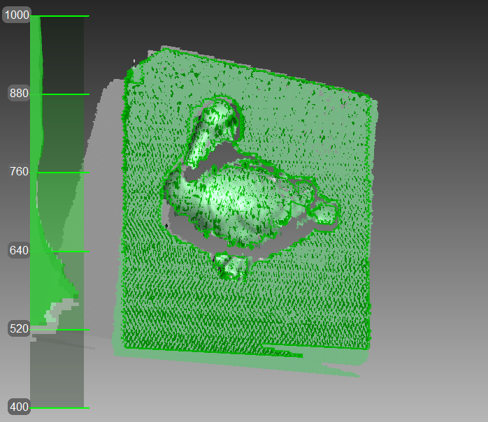
Figure 47 Main window when using Geometry tracking to scan objects.
- Targets
- A special algorithm for scanning objects with special targets placed on their surfaces.
- Real-time fusion (option)
- Available for both Artec 3D scanners and third-party 3D sensors, this option fuses the results immediately after scanning.
See also
Base Removal: Erasing a Supporting Surface
- Base removal is available for all tracking modes.
- If you click Stop or press , you should again identify the supporting surface.
- If the scene remains unchanged, you can also use the Auto-align new scans with those marked in Workspace option. In this case, the application won’t prompt you to identify the base.
- If base detection is successful, the base will always render in Recording mode.
When you capture an object, you can often omit from the scan any surface that supports the object. The Base removal option serves this purpose. To employ this option, first indicate the surface on which the object is resting and then capture the object. If this approach is unsuitable for your situation, clear the Enable automatic base removal checkbox.
Open the Scan panel.
Make sure the Enable automatic base removal checkbox is selected.
Click Preview and direct your scanner at the surface that supports object (e.g., a table or the floor). A gray wireframe plane will appear, indicating the scene’s base.
Once the application detects the base, it will display a message: “Now scan the object.”
Important
If Artec Studio fails to detect a supporting surface, you can still start recording.
Direct the scanner at the object and click Record (
)Scan the object freely. You can pause and resume the session as necessary.
Click Stop; all scans will move to the coordinate system with the Z axis normal to the base.
Close the Scan panel. After Artec Studio performs Fine registration, the Base removal algorithm will remove the previously detected supporting surface. If not, erase it manually.

Figure 48 Scanning with the Enable automatic base removal option.
Resuming Scan After Lost Tracking
Artec Studio records adjacent frames on the basis of common surface features. If the scanner stops recognizing common features, it will stop capturing the scene. This situation is called lost tracking; if it happens, just direct the scanner at a recently captured region. There are, however, nuances, which we address below.
Table 2 lists several causes of lost tracking. The most common is moving the scanner too fast.
| Reason | Possible Solutions |
|---|---|
| Moving the scanner too fast | Move the scanner more slowly or increase the Scanning speed |
| Scanner sees too few surfaces | Apply an anti-glare spray or direct the scanner at a larger part of the object; increase Sensitivity of Artec Spider |
| Object doesn’t have enough features for successful tracking | Apply masking tape or draw markers on the surrounding surfaces, and/or move the scanner more slowly |
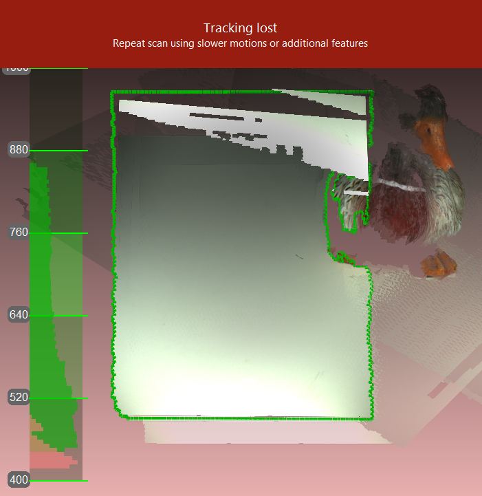
Figure 49 Alert message: tracking lost.
The Scan using auto-alignment option may ease the process of resuming tracking (this option is enabled by default in the application settings). Note the following:
Artec Studio switches almost instantly from displaying Tracking lost mode (see Figure 49) to Searching for position, which appears on a green background.
To continue scanning, direct the scanner at a region you’ve already captured.
- Try to maintain the original scanner orientation toward this region
- You need not necessarily use the most recent one, but it should have sufficient texture features.
If the application successfully resumes tracking, it will start recording in a newly created scan. This new scan will already be aligned with the previous one.
The Scan Using Auto-Alignment section describes system behavior when this option is disabled.
Auto-align new scans with those marked in Workspace
Auto-alignment is a great timesaver and may help simplify further processing. But for projects that involve scans using Geometry + Texture tracking and for which the actual scene is unchanged, you can continue scanning immediately:
- Ensure that the Scan using auto-alignment option is turned on in Settings (see Capture).
- Mark previously captured scans using the
 icon in the Workspace panel.
 - Select Geometry + Texture tracking as well as the Auto-align new scans with those marked in Workspace checkbox in the Scan panel.
- Click Preview, direct the scanner at a textured region you’ve already captured textured region—maintaining the original scanner orientation—and then click Record.
- If tracking resumes successfully, Artec Studio will align the newly recorded scan with the selected ones.
Scanning With Real-Time Fusion
Real-time fusion is a special mode in which Artec Studio builds a 3D model in real time while you’re scanning. It’s the easiest and fastest way to obtain a model, but it cannot completely replace the normal workflow for processing raw scans after capturing them. Thus, we recommend avoiding Real-time fusion in the following cases:
- The scene is large and the amount of GPU memory is limited
- Objects have complicated shapes that cannot be captured in one scan session
- The object has small geometric details
- Extra-high accuracy is required
The Real-time fusion feature is available for each tracking method.
- Open the Scan panel.
- Select the required tracking mode.
- Select the Real-time fusion checkbox [2].
- Click Preview and then Record. Observe the recommendations in Scanning Procedure.
- Pause and resume the session as necessary.
- When you stop scanning, the Workspace panel will add one or more raw scans named
Eva Scan1,Eva Scan2,Eva Scan3and so on, as well as one model namedEva Scan1-Fusion. The number of these raw scans corresponds to how many times you pause and resume scanning (see Figure 50).
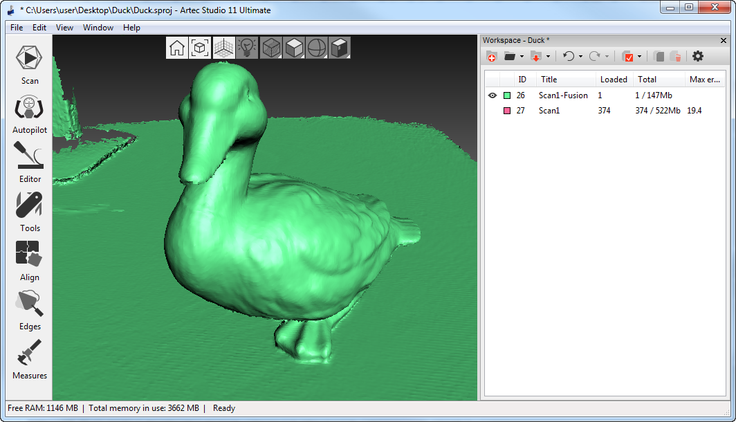
Figure 50 Workspace panel after using Real-time fusion.
You can access the Settings window and use the Performance tab to configure the following Real-time fusion settings (see Real-Time Fusion Settings):
- Voxel size
- 3D resolution of the model (i.e., the size of the triangulation-grid step in millimeters). The smaller the value, the more geometric details you can detect and capture in 3D.
| [2] | If you selected the Targets mode and cleared the Disable hybrid tracking for .obc checkbox (see the Photogrammetry Settings section), Artec Studio will clear the Real-time fusion checkbox because it doesn’t support this combination of options. |
Target-Assisted Scanning
Generally, you don’t need any special equipment to record using an Artec scanner. If the object has hard-to-scan regions, however, targets may be useful. In some cases, they can improve tracking and further registration.
Placing Targets
Whatever the method chosen, you should place at least non-coded targets on the object.
Attach non-coded targets (Figure 51) to the object using the following rules:
- Try to place them on flat elements
- Avoid uneven surfaces
- Avoid obstructing significant geometric elements
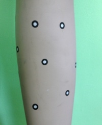
Figure 51 Non-coded targets placed on an object.
Note
You can specify the target size in the Settings dialog of Artec Studio, as Photogrammetry Settings describes. If you use non-coded targets from the Scan Reference kit, specify 5 mm for the inner diameter and 10 mm for the outer diameter. You should measure targets from other suppliers and specify both diameters in the appropriate fields of the Settings dialog.
Place coded targets if your choice is photogrammetry (Using Photogrammetry Solution (Scan Reference)).
- Prepare the objects and surrounding scene. All objects must remain stationary during measurement and capture.
- Place the cross (Figure 53) on the scene, ensuring that it rests firmly, and it is seen from most points of view. Also double check that all targets on the cross are clearly visible.
- Place the coded targets on the object and the surroundings. Note that you should distribute them such that at least six to eight coded targets are visible in each image. Random placement is preferable; avoid symmetry and target alignment.
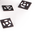
Figure 52 Coded targets.
Using Artec Scanners Only
You don’t necessarily need a photogrammetry kit to benefit from targets placed on the object you’re scanning; Artec 3D scanners can do all the work. This mode employs extra-hybrid (Geometry + Texture + Targets) tracking and doesn’t require you to upload an OBC file.
- Open the Scan panel in Artec Studio. Select Targets under Features to track.
- Scan the object from all sides
- Run Global registration
Note
As you scan (without having uploaded an OBC file), the application registers the target coordinates. You can then save an OBC file and use it in later scanning sessions. We strongly recommend running Global registration first, however.
Using Photogrammetry Solution (Scan Reference)
By using a combination of special reference targets and photogrammetric measurements, you can scan large areas in one session, improve the accuracy of captured surfaces and boost productivity by reducing postprocessing time. The only downside of this method is the preparation. After scanning, however, you need not align the scanned surfaces, so you can immediately proceed to Fusion (see the order of postprocessing steps in 3D Scanning at a Glance).
This synergy of technologies is possible thanks to Artec 3D-scanner and photogrammetry solutions. Several third-party photogrammetry offerings are available on the market. Scan Reference photogrammetry is one example. The Scan Reference kit includes hardware and software (see Figure 53), a digital camera, a reference-scale cross, non-coded sticky targets (which Artec Studio uses to match the captured 3D data to the photogrammetric measurements), and reusable magnetic coded targets (required to automatically carry out measurements in the Scan Reference software).
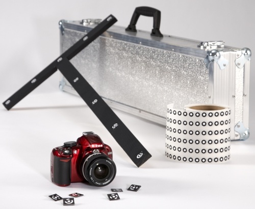
Figure 53 Scan Reference kit
To perform scanning using targets, follow these steps:
- Take several photos of the object from different angles. To determine the appropriate number of photos, angles and targets for each image, as well as required settings for a calibrated digital camera, consult the Scan Reference user manual and FAQ article. General recommendations are as follows:
- Take photographs at a distance of 0.5–1.5 meters with enabled flash
- Each photograph should contain as much targets as possible and each target should be captured at least in 10 photos
- Entire cross should be captured in first 10–12 photographs
- Capture the object from all sides
- Move the cross and the coded targets away from the scene.
- Connect the camera to a PC, then transfer and process the photos using the Scan Reference software. Once the calculations are complete, the software will display measurement results on the screen. These results can appear as a point table or a 3D model.
- Save the point model in an
*.obcfile. This format is the software’s default. - Open the Scan panel in Artec Studio. Select Targets under Features to track.
- Click Load targets from file and specify the
OBCfile path. - Scan the object. When you finish, the software will align all scans.
Important
If you don’t want the texture and geometry features to assist target scanning, select the Disable hybrid tracking for .obc checkbox (Photogrammetry Settings).
Using Certain Scanner Types
Notes on Scanning With Spider
Because Artec Spider has smaller field of view and provides higher accuracy in comparison with Artec EVA, scanning using it can pose difficulties. Consider the recommendations given in Technique and also the following:
- Opt for rotating table if possible
- Use a piece of paper with text on it as artificial texture
- Double check that objects don’t change their shape and position
- Try tuning sensitivity in particular cases (see Sensitivity). Avoid extreme values.
We recommend using the Artec Spider scanner only after it reaches its normal operating temperature. As soon as you plug Artec Spider in or connect it to a PC, it starts warming up. If you open the Scan panel, you will see two lines that provide the device’s current and optimal temperatures. Artec Spider will warm up faster when it’s in Preview mode. The Scan panel also displays additional information about the time remaining until the scanner reaches its optimal temperature.
Note
Artec Spider can operate at temperatures beyond its optimal range, but the accuracy of captured surfaces may be lower.
Notes on Scanning With Third-Party 3D Sensors
Important
Support for third-party 3D sensors is only available in Artec Studio Ultimate.
Third-party 3D sensors (see Devices’ Appearance) are not specifically designed to serve as 3D scanners. Because they are multipurpose devices made from inexpensive components, they can scan objects, but the texture and surface quality is far worse than that of professional Artec 3D scanners (see Figure 54). The operating ranges and fields of view for all Artec Studio Ultimate–supported third-party sensors are shown in Figure 19.
When using third-party 3D sensors, bear in mind the following:
- Providing good lighting is critical
- because none of the sensors offers built-in flash. Also, use of these devices precludes the ability to adjust the brightness of the texture you are scanning, so good lighting is crucial to obtaining a decent model. Avoid using too much illumination, and avoid using direct light or fluorescent lamps. Intel RealSense R200 is particularly sensitive to direct sunlight.
- When using PrimeSense and Asus Xtion sensors,
a special technique can help you capture surfaces with consistent brightness:
- Click the Preview button
- Direct the sensor at the object and hold it for 5 seconds while the sensor adjusts white balance and exposure
- Click the Record button
- Move the scanner slowly to capture the scene
- While scanning, keep the sensor as close to the object as possible
- Most third-party devices work in the Real-time fusion mode,
- except for Kinect v2. Moreover, this mode is default for Intel RealSense 3D sensors.
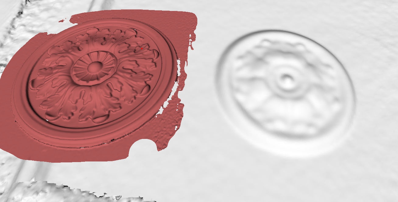
Figure 54 Object captured and processed
Notes on Scanning With MHT
The flash feature in an Artec MHT scanner has a very large but limited number of operation cycles, so ensure that you disable the scanner when it’s not in use. Avoid leaving the Artec MHT on for a long time when using the maximum capture rate (15 frames per second). Artec Studio will automatically turn off the Artec MHT after five minutes of continuous operation. Normally the active mode/rest mode is 3 minutes of scanning and 7 minutes of rest; this mode is optimal and significantly increases the lifetime of the flash.
Tweaking Scanning Options
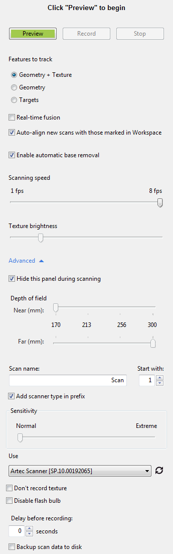
Figure 55 Scan panel in Artec Studio.
Tuning Texture Brightness
Note
This option is available only for Artec 3D scanners equipped with texture cameras.
You can adjust the Texture brightness setting in Preview mode. Use the slider to increase or decrease the brightness of frames captured by the color camera (see Figure 56). Note that the texture brightness affects texture quality as well as tracking steadiness. Observe the recommendations in the Table 3.
| Surface Color | Recommendation |
|---|---|
| Dark or black | Increase brightness |
| Light-colored or white | Decrease brightness |
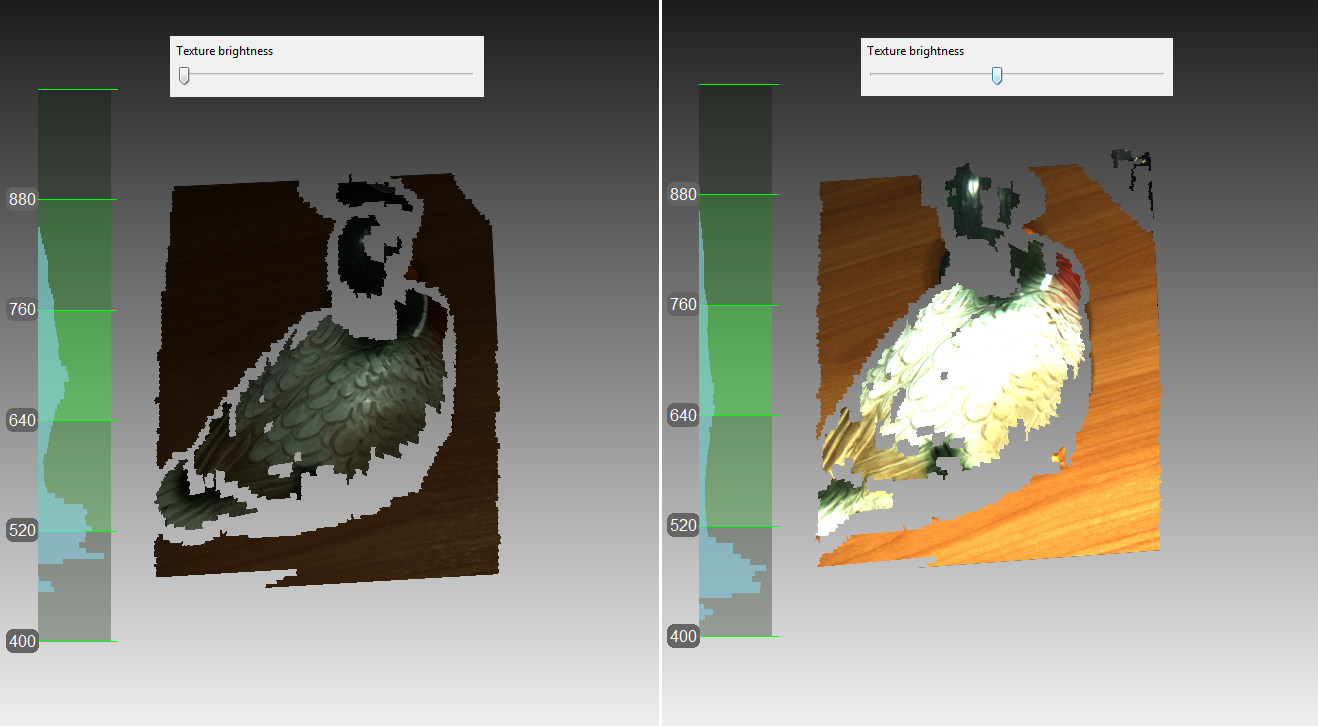
Figure 56 Color-camera brightness adjustment
Sensitivity
You can tune the Sensitivity of Artec Spider scanner if the application fails to reconstruct particular surfaces. Increasing this setting enables the scanner to more easily capture black, reflective, translucent and fine objects (such as human hair). The higher the sensitivity, the noisier the recorded surfaces will be. Higher values may also reduce the scanning speed. For Eva and other Artec scanners, this setting is automatically adjusted.
Frequency for Capturing Texture Frames
Specify the frequency for capturing texture frames by using the corresponding spinner in the Settings dialog (see Texture-Recording Mode and Figure 152).
Deactivating Scanner Flash
If circumstances prohibit you from using the scanner flash, follow the directions below.
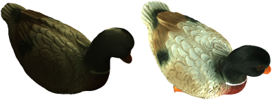
Figure 57 Influence of ambient light on captured results.
Note that if you disable the flash, you should compensate by using bright ambient light. According to our tests, acceptable texture quality is obtainable with the flash disabled if the surface illuminance is at least 1 000 lux. Compare the models shown in Figure 57, which were recorded under different lighting conditions.
The following procedure captures the textured model without using the scanner flash:
- Open the Scan panel and click the Advanced link
- Turn off the texture flash by selecting the Disable flash bulb checkbox
- Use good illumination. Avoid fluorescent lamps.
- Click Preview and direct the scanner at the object
- Adjust Texture brightness and Texture exposure time. In most circumstances, values should be as low as possible, because increasing the brightness also increases a texture noise, whereas increasing exposure time can blur the texture. Instead of adjusting sliders, try to further improve the lighting conditions.
- Capture the scene
- Perform required postprocessing as described in Data Processing to get a textured model
- Adjust texture parameters for this model as described in Texture Adjustment. Pay particular attention to the Hue and Saturation sliders. The Hue slider allows you to correct unwanted texture color.
Tuning Exposure Time
You can alter texture exposure time in the Preview mode. Adjust this parameter in tandem with the Texture brightness. Increasing exposure time can blur the texture. Don’t alter the default value unless it’s necessary.
Disabling Texture Recording
Clear Don’t record texture checkbox if you don’t want to store texture information in your scans. It is located in the Advanced section of the panel and disengages both texture camera and texture flash in the scanner. Note that this option is unavailable for Artec EVA Lite. Don’t forget to select this checkbox once you have completed textureless scanning; otherwise, next time you want to start regular scanning the hybrid tracking mode could be unavailable.
Important
Just using the Geometry tracking mode it is still not sufficient for the application to don’t record texture. Make sure you clear the eponymous checkbox.
Decreasing Scanning Speed
Artec EVA captures objects at up to 15 frames per second, whereas Artec Spider at 7.5. Default values ensure comfortable scanning with smooth movements. However, if you find scanning speed inappropriate, you can decrease it. In this case, Artec Studio will record fewer identical frames and register them faster. To this end, use the Scanning speed slider in the Scan panel.
Important
Decreasing scanning speed may hinder scanning. Don’t use this slider unless it is absolutely necessary.
Supplementary Settings
- Customize scan names and starting number
- by entering your own values in the Scan name and Start with fields and changing the state of the Add scanner type in prefix checkbox. The software uses these values to create a scan title in the Workspace panel (see Figure 80, left). You can change the default values
Eva Scanand1to, for example,Captureand14. - Set backing up scan data to disk
- Trigger a capture mode that simultaneously records scanning results to a disk by selecting the Backup scan data to disk checkbox. This option is enabled when you’re working with an existing saved project (see Saving a Project) and can be useful when capturing large amounts of data on a computer with insufficient RAM.
- Specify a delay (in seconds) before recording
- using the Delay before recording spinner under the Advanced section of the Scan panel. The countdown begins as soon as you click the Record button. To eliminate the delay, set the value to zero.
- Decrease specified operating-zone (Depth of field)
- by using the Near (mm) and Far (mm) sliders under the Advanced section of the Scan panel. Here you can only decrease range within the specified boundaries.
- Specify the operating-zone boundaries (in millimeters)
By default, Artec Studio provides the correct values for the minimum and maximum limits within which the cutoff planes are to be positioned. These values are different for each 3D scanner model, and they ensure that you capture good-quality 3D data. If high accuracy is a secondary concern, you can manually adjust the depth boundaries, allowing you to capture objects using an Artec L scanner or third-party 3D sensors positioned closer to or further from the object than is recommended. To do so, select the Override default depth range checkbox in the Settings dialog in the Scan tab, then specify new boundaries for the scanning range (For more details about scan settings, see Capture).
Warning
Custom depth-range settings may reduce accuracy.
- Configure hiding Scan panel during scanning
- To widen the viewport during scanning, software automatically closes the Scan panel once you start recording using Artec EVA or Artec Spider scanners. The Hide this panel during scanning checkbox is located in the Advanced section and is cleared by default.
Troubleshooting
| Issue | Possible Resolution |
|---|---|
| Geometry + Texture radio button missing from Scan panel. | You were probably scanning without texture. Clear the Don’t record texture checkbox in the Advanced section. |
| Final model contains noticeable noise. | You likely scanned the affected areas improperly, or the scanner was too far from the object. Rescan those areas. |
| Tracking lost error persists. | Make sure Scan using auto-alignment is enabled in the Settings dialog and use Geometry + Texture tracking. |