Workspace and More
Artec Studio User Interface
Windows, Panels and Bars
When you launch Artec Studio, you will see the main application window, which allows you to perform all operations on scans and models.

The main window is divided into several sections:
Section |
Intent and other information |
|---|---|
|
Display all 3D data. |
|
Quickly orient objects. |
|
Alter 3D-data appearance and toggle display of coordinate grid. |
|
Quickly access to the set of tools for working with objects geometry and transformations. |
|
List and manage 3D objects as well as toggle their display and availability for tools. |
|
Displays detailed information for 3D objects. / Displays information about captured targets for scans with global registration applied. |
|
Store records of any executed commands, specifying the time and details of each operation (error and troubleshooting messages). |
|
Contains information on memory availability and current usage by Artec Studio. It also has a progress indicator for any currently running task, such as algorithm execution, model and scan exporting, and so on. |
|
Accommodate panels for various application modes, including Scan, Autopilot, Editor, Tools, Align, Fix holes, Texture, Construct, Measures, Settings, History and Feedback. |
|
Toolbar to start the above mentioned modes. |
|
Dropdown menus with various commands. |
If any of the panels are hidden, go to the Window menu on the Menu bar, and select the panel to display it. If Quick toolbar is hidden or some of the tools are disabled, it means that your projects doesn’t contain any supported objects.
You can also quickly show or hide some of the panels/toolbars (namely, Left toolbar, Workspace panel and Log window) by clicking on the special bars marked with double arrows: ![]() ,
, ![]() ,
, ![]() ,
, ![]() . These bars are located along one of the borders of the corresponding panel or toolbar.
. These bars are located along one of the borders of the corresponding panel or toolbar.
You can minimize or maximize the right-side panels by clicking on the (-) or (+) icons on the upper right corners, respectively.
Note
The Workspace, Features, Quick toolbar, and Properties panels are detachable, and can be moved around and placed anywhere on the window. Simply drag-and drop, or click on the  on the upper right corner of the panel, and drag.
Primary Settings
To access the settings dialog, select Settings… in the File menu. The settings window has several tabs for various groups of application settings. To switch between the tabs, click the icon at the top of the dialog. For a detailed description of the tabs, see Settings.
To change the language, select the Miscellaneous tab (Figure 202) and then the required language from the list and click OK. You will be asked to confirm the operation and restart the application. Once you agree, Artec Studio will automatically restart using the new interface language. If you choose not to restart, the changes will be applied the next time you start the application.
Important
By default, the 3D view window functions in the normal camera mode. However, you can switch to Orbit camera mode by selecting the Orbit Camera option in the View menu.
Workspace Panel
Object Types
After each scanning iteration, Artec Studio saves a separate scan. The list of all scans for a given project appears in the Workspace panel (see Figure 66). Afterwards, the algorithms, primarily fusion, yield models.
Artec Studio can accommodate the following types of objects in Workspace:
Type |
Icon |
Content |
Origin |
|---|---|---|---|
Scan |
|
Set of frames |
From scanners Eva, Spider, Leo, Micro, and Micro II |
HD raw data |
|
Set of HD frames |
From Eva scanner |
Point-cloud scan |
|
Point cloud |
From Ray and Ray II scanners |
Model |
|
Polygonal mesh |
Algorithm output (fusion) or imported mesh |
CAD model |
|
CAD model |
Imported |
Cylinder |
|
CAD primitive |
Created in Artec Studio (see Constructing CAD Primitives) |
Cone |
|
CAD primitive |
Created in Artec Studio |
Plane |
|
CAD primitive |
Created in Artec Studio |
Sphere |
|
CAD primitive |
Created in Artec Studio |
Torus |
|
CAD primitive |
Created in Artec Studio |
Freeform |
|
CAD primitive |
Created in Artec Studio |
Targets |
|
Target cloud |
Imported |
Group |
|
Group of objects |
Grouping of objects listed above |


See also
Object Columns
Object data in the Workspace panel is arranged in several columns:
|
Scans marked with |
Icon |
Each type of objects has a specific icon (see Table 4). This icon is always displayed to the left of the object or group name for improved visual perception of information in the Workspace panel. |
Name |
When a scan is created, Artec Studio automatically assigns it a name, such as |
Color |
In this column, each object has a colored square (for example, |
Type |
The type of an object. See here for details. |
Error |
The largest registration-error value among all frames in the scan. More information. |
Frames |
The total number of frames constituting the scan. |
Scanner type |
The type of the scanner that created the object. |
Texture frames |
The number of captured texture frames. See Texturing for details. |
Polygons |
The number of polygons constituting the object. |
Locks |
Algorithms will not reposition the frames of the scans marked with |


Figure 66 Workspace panel and respective context menus: object list on left and surface list on right.
Use the  button at the top left to select the columns to be displayed or to hide the panel.
Change the column order by drag-and-dropping their headers.
button at the top left to select the columns to be displayed or to hide the panel.
Change the column order by drag-and-dropping their headers.
Note
The columns marked with  and
and  appear automatically if you set the Lock object or Lock frames status respectively, for one or more objects using the context menu (see Operations with Objects for details on the context menu operations).

Figure 67 Selecting columns to be displayed, and filtering objects.
Operations with Objects
In the Workspace panel, you can perform various types of operations with objects. All types of operations are available through the context menu called by clicking RMB on some object.
Menu Item |
Description |
|---|---|
ALL OBJECTS filter |
Instruct Workspace to display only particular types of the objects or all of them (see Figure 68). |
Select all |
Select (highlight) all objects for further operations on them. If only one or several objects of one group are selected in Workspace, the first run of this command will select all group objects, the second – all Workspace objects. |
Deselect all |
Reset any selection |
Invert selection |
Reset the current selection and select all other objects. |
Group / Ungroup |
You can group a few objects in the workspace according to some feature. Select required objects, call the context menu by clicking RMB and select Group. You will see that the objects are wrapped with a common header (for example, Group 1), which can be changed as well as the object names (see below). It is possible to create subgroups within groups. Resumed scans are also grouped automatically during scanning. Each scan imported from Leo will be included in a separate group inside the project group. See also Actions with Groups. |
Rename |
Select an object by clicking LMB on its name, hit F2 and specify a new object name in the opened dialog window. You can also rename many objects at once: select multiple objects (as described above) and then use F2 or RMB to rename them. |
Duplicate |
To make a complete duplicate of an object in the Workspace, right-click on the object and then select Duplicate.
A copy of the object will be created with the name like |
Show |
Display the selected objects in the 3D View section. See Selecting Scans and Models for details. |
Hide |
Do not display an object in the 3D View section (cancel the Show operation). |
Lock frames |
Set the Locked frames status ( |
Lock object |
Set the Locked object status ( |
Unlock |
Remove the Locked frames and Locked object statuses from an object. |
Change color |
Call the color palette to change the color of an object or a group. See also Actions with Groups. |
Copy transformations |
Save the transformations of a scan and its frames for their further transfer to another scan. See Transferring Transformations for details. |
Unregister |
Reset the positions of individual frames in a scan computed during its registration. See Separating Scans for a use case. |
Delete |
Delete objects from your project. |
Upload to Cloud |
Upload fusions and models to cloud directly from Artec Studio. See Exporting to Artec Cloud for more information. |
Any column header |
Sort the objects by either of their properties. Clicks: ascending order → descending → initial. |

Figure 68 Filtering objects in Workspace.
Actions with Groups
In the Workspace panel you can perform the following actions with the groups of objects using the elements of the group header row:
Action |
How to perform |
|---|---|
Select/Deselect |
To select or deselect all objects in a group, click the group row in the column marked with |
Set/Change group color |
By default, the group color is not set ( |
Unset group color |
To cancel the color setting for a group, right-click the group row in the Color column area. |
Lock |
To lock or unlock all objects or frames in a group, click the group row in the Lock column area ( |

Selecting Scans and Models
To view a scan or model in the 3D View window or to process it, you need to mark it with the  icon in the Workspace panel. To navigate scans and models, use keys ↑ and ↓ or click an arbitrary area except those in , or color column (
 ).
).
Purpose |
Method |
Alternate Method |
|---|---|---|
Highlight an object in Workspace to view its properties or run a command from the context menu |
Left-click on the scan name |
— |
Toggle visibility and availability for processing (flag |
Left-click in the |
|
Batch selection (deselection) of objects for display and processing |
Click |
|
Select a single object for processing and deselect others |
Select the object name using Ctrl+Alt+LMB |
Use Ctrl+LMB in the empty area of the |
In addition to the methods in the table above, you can use commands from the context menu by clicking RMB on the objects.
See also
The full list of hot keys in workspace.
Selecting Frames
Double-clicking on the scan name (or using the View frames command in the context menu) opens a list of all the frames in that scan (see Figure 66, right).
Manually selecting specific frames will make them (and only them) appear in the 3D View window. Alternatively, to select a particular frame directly on the 3D View window, without the need for manually browsing through the frames list, simply click LMB while holding the Alt key.
You can select frames in a number of ways:
Click LMB on the frame name to select it while clearing other selections.
Click LMB while holding the Ctrl key to select several frames at once.
Click LMB while holding the Shift key to select a sequence of frames in the specified range.
Click Ctrl+A/Ctrl+D to select/deselect all frames.
Click LMB while holding the Alt key to select a frame directly from the 3D View window. This will display only the selected frame in the 3D View window.
To start a sequential frame demonstration, use the  button at the upper right of the Surface list. To stop the demonstration, click
  .
.
Object Properties
At the bottom of the Workspace panel, you can see a Properties panel. Click on it to expand it. Then select any object to display its properties. Depending on the selected object, its properties are displayed under the Basic and Advanced tabs.
In the Advanced tab, you can view details of a scan like number of Polygons or Size of the scan and Scanner ID.

Figure 69 Basic and advanced object properties of a selected scan.
If no object is selected, the global settings of the project will be displayed in the Properties panel.

Figure 70 Project properties when no object is selected.
Features
By default the Features panel is located at the bottom of the Workspace panel near the Properties panel. Click on it to expand it. Then select one or more scans with the global registration applied and/or a reference target cloud to display the features of the captured targets.
See Features Panel for details. If no object is selected, the Features panel will be empty.
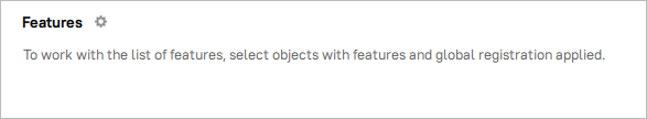
Figure 71 Features without a selected object.
Selecting a Point-Cloud Scan
Point-cloud scans contain only one surface. Click LMB on a point-cloud scan and look at the Properties section:
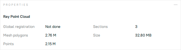
Figure 72 Properties of the point-cloud scan.
Parameter |
Description |
|---|---|
Global registration |
Shows whether the global registration procedure has been performed. |
Mesh polygons |
Since Artec Studio doesn’t display all the points constituting the scan, you can only see a mesh obtained from a simplified copy of the actual point cloud. |
Points |
Total number of points in the point cloud. |
Sections |
When you scan with Ray, you may select particular regions (sections) to narrow down the actual scene. This parameter stands for the number of these regions. |
Quick Toolbar
You can get access to the most frequently used tools for CAD and other objects using quick access Quick toolbar. The presence of tools on the Quick tolbar and their accesibility directly depends on the objects existing/being selected in your project.
Tool |
Icon |
Summary |
Supported objects |
|---|---|---|---|
Transformation |
|
Allows to move, rotate, scale and mirror objects relative to the global coordinate-system axes. Same as Editor → Transformation tool. |
All visible |
Cross section |
|
Creates a dynamically adjustable cutting plane. |
Scans, Models, CAD objects, Point clouds. |
Chamfer |
|
Creates a transitional surface between two adjoining object faces at a certain angle depending on set distances. Symmetrical/asymmetrical. |
CAD objects. |
Fillet |
|
Creates a rounded smooth curve joining two object faces depending on set distances. Symmetrical/asymmetrical. |
CAD objects. |
Draft |
|
Modifies the angle of object surface. |
CAD objects. |
Thickness |
|
Adds thickness to object by offsetting surfaces inward or outward, or in both directions. |
Models, CAD objects. |
Move surface |
|
Move the selected surface by a specified offset. |
CAD objects. |
Deviation analysis |
|
Calculates the deviation of two objects and asseses the result of the fitting and aligning geometry tools. Same as Measures → Distance map. |
Models, CAD objects. |

Cross section
To create a cross section,
Mark the
checkboxes of desired object in the Workspace to which you would like to apply the Cross section tool on the Quick toolbar.Click the Cross section (
 ) icon on the Quick toolbar to open the Cross section tool. The Cross section tool will open in a pop-up, which is draggable and can be located at any place in the 3D view window.
Select one of the available coordinate planes (YOZ
 , XOZ
, XOZ  , XOY
, XOY  ). Once the coordinate plane is selected, you will see the preview of a cross section.

Figure 73 Cross section on YOZ coordinate plane.
Z-axis is always perpendicular to section.
To customize cross section,
Move section along its normal (Z-axis) by clicking LMB on the arrow and dragging it.
Flip the direction of cross section by clicking Flip direction button

Figure 74 The flipped cross section on YOZ coordinate plane
Note
Even after the cross section is generated, you can switch to another coordinate plane.
To enhance visibility by filling section with color, toggle the Show cap switch on.
Keep in mind that showing caps is only available for CAD objects and models.

Figure 75 Cross section with colored cap.
Apply changes by clicking on the Save as section button. Your saved section will appear on Measures panel along with other measures.
Chamfer
To create a chamfer,
Mark the
checkboxes of desired CAD object in the Workspace to enable Chamfer  tool on the Quick toolbar.
Click the Chamfer (
) icon on the Quick toolbar to open the Chamfer tool. The Chamfer tool will open in a pop-up, which is draggable and can be located at any place in the 3D view window.Click LMB on the desired edge of the CAD object. The hovered edge will be highlighted in yellow. Once it’s selected, you will see a preview of the default chamfer.

Figure 76 The default symmetrical chamfer at 45°angle.
To customize the created chamfer,
Set the value of distance from initial edge to the new edge on the first surface to the Distance 1 field. If the Symmetrical switch is toggled, the value entered in the Distance 1 field will also be applied to the Distance 2 field.
To make the created chamfer assymetrical, toogle the Symmetrical switch off and enter custom distances in the Distance 1 and Distance 2 field.
To adjust the shape of chamfer corner, try different values of Corner Form parameter
To spread the chamfer to the neighbouring edges that are smoothly connected, use Tangent propagation parameter
Apply changes by closing the Chamfer tool.

Figure 77 Chamfer with Tangent propagation parameter off.

Figure 78 Chamfer with Tangent propagation parameter on
To reset your changes, click Reset icon ( ). All changes will be undone.
Fillet
To create a fillet,
Mark the
checkboxes of the desired CAD object in the Workspace to enable the Fillet  tool on the Quick toolbar.
Click the Fillet (
) icon on the Quick toolbar to open the Fillet tool. The Fillet tool will open in a pop-up, which is draggable and can be located at any place in the 3D view window.Click LMB on the desired edge of the CAD object. The hovered edge will be highlighted in yellow. Once it’s selected, you will see a preview of the default fillet.

Figure 79 The default symmetrical fillet.
To customize the created fillet,
Set the value of distance from initial edge to the new edge on the first surface to the Distance 1 field. If the Symmetrical switch is toggled, the value entered in the Distance 1 field will also be applied to the Distance 2 field.
To make the created fillet assymetrical, toogle the Symmetrical switch off and enter custom distances in the Distance 1 and Distance 2 field.
To adjust the shape of fillet corner, try different values of Corner Form parameter.
To spread the fillet to the neighbouring edges that are smoothly connected, use Tangent propagation parameter.
Apply changes by closing the Fillet tool.
To reset your changes, click Reset icon (). All changes will be undone.
Thickness
To thicken an object,
Mark the
checkboxes of the desired mesh or CAD object in the Workspace to enable the Thickness  tool on the Quick toolbar.
Click the Thickness (
) icon on the Quick toolbar to open the Thickness tool. The Thickness tool will open in a pop-up, which is draggable and can be located at any place in the 3D view window.To adjust the thickness, set the desired value in either the Forward or the Backward field, or assign different values to both fields by turning off the Symmetrical switch.

Figure 80 The Thickness tool with a 5mm forward and backward offset
Draft
To create a draft,
Mark the
checkboxes of the desired CAD object in the Workspace to enable the Draft  tool on the Quick toolbar.
Click the Draft (
) icon on the Quick toolbar to open the Draft tool. The Draft tool will open in a pop-up, which is draggable and can be located at any place in the 3D view window.Select one or multiple adjacent faces connected to the base for which the draft will be specified.
Set the draft angle in the Angle field.
Click the Apply button to save the created draft (see Figure 81).

Figure 81 The created draft at 20°angle
To reverse the direction of the base surface, click the Reverse ( ) icon in the Draft pop-up. The surface draft will be flipped.
Move surface
To move a surface of the selected CAD object,
Mark the
checkboxes of the desired CAD object in the Workspace to enable the Move surface  tool on the Quick toolbar.
Click the Move surface (
) icon on the Quick toolbar to open the Move surface tool. The Move surface tool will open in a pop-up, which is draggable and can be located at any place in the 3D view window.Select any surface of the CAD object. Shift-click to select multiple surfaces.
Set an offset value to the Distance field.
Specify an offset axis (optional).
Click Apply button to save changes. The selected surface is moved.

Figure 82 The Move surface tool with a 50mm offset - Not applied yet.
Deviation analysis
In Artec Studio there is a number of tools that fit the geometry of one object into another or align them:
Fit all kinds of primitives
Fit Freeform surfaces
Best-fit
Autosurface creation
Deviation analysis tool calculates the distance map showing the deviation of the initial and fitted surfaces. Deviation analysis can be performed between CAD and model or two models.
To enable the tool,
Mark the
checkboxes of the desired CAD object and model, or two models in the Workspace to enable the Deviation analysis  tool on the Quick toolbar.
Click the Deviation analysis (
) icon on the Quick toolbar to open the Deviation analysis tool. The Deviation analysis tool will open in a pop-up, which is draggable and can be located at any place in the 3D view window.
Note
If you selected only one object, the Deviation analysis tool will be enabled, but you will see the text prompt to select at least two objects. If invalid objects are selected, Deviation analysis tool will remain disabled.
Once you’ve selected the valid objects for calculating the deviation, the algorithm will run automatically, the Deviation analysis pop-up will open.

Figure 83 The Deviation analysis tool with calculated distance map
By default, Search distance is 1 mm but you can also recalculate by entering a desired Search distance (in mm) value and click the Recalculate button. For more information about Distance map parameters, refer to the Distance Maps section.
See also
The Deviation analysis tool is the same as Measures → Distance map and can also be performed in the Datum Alignment mode. See Datum Alignment for more details.
Memory Management: Smart RAM Usage
Working with a large data set requires a huge amount of RAM and you might often find it necessary to free up RAM without deleting any of the project data. While the previous versions of Artec Studio tackled this by making it possible for you to load or unload scans manually, the new Artec Studio 16 automatically optimizes RAM usage through smart memory management.
When you open a project, all the scans are preloaded into the RAM and displayed in the Workspace, which enables you to start working with them immediately. When you select one or more scans in the Workspace, Artec Studio will automatically load only the selected scans. If a particular algorithm or action requires any scans, the application will automatically load them into RAM too. Likewise, Artec Studio will automatically unload unnecessary scans, frames, textures or a combination thereof. This selective loading and unloading of data frees up extra RAM automatically.
Note
In addition to 3D data, the change history can also consume a large portion of memory. For information on how to control the history size as well as how to clear it, consult History of Project Changes.