Scanning
Imaging
The scanner has two different types of image sensors:
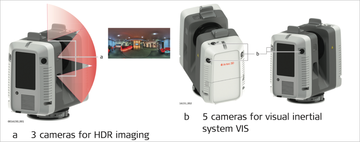
Figure 18 Ray II - Image sensors.
Three calibrated cameras for HDR, 360° spherical image acquisition.
Five calibrated cameras for the visual inertial system VIS.
Conditions
Unfavourable surfaces for scanning:
Highly reflective (polished metal, gloss paint)
Highly absorbent (black)
Translucent (clear glass)
Note
Colour, powder or tape these surfaces before scanning if necessary.
Unfavourable weather conditions for scanning:
Rain, snow or fog may adversely affect measurement quality. Always use care when scanning in these conditions.
Surfaces that are directly illuminated by the sun cause an increased range noise and therefore a larger measurement uncertainty.
If some objects are scanned against the sunlight or a bright spotlight, the optical receiver of the scanner can be dazzled so heavily that in this area no measured data is recorded.
If the scanner is brought from a cold environment, for example from storage, into a warm and humid environment, the mirror or in extreme cases even the interior optics can condense. This may cause measurement errors.
Warning
Avoid rapid temperature changes and give the scanner time to acclimatise.
Due to the encapsulated mirror design, the mirror is protected against direct contact. However, dirt on the rotating mirror protection glass such as a layer of dust, condensation or fingerprints may cause considerable measuring errors.
Field of view
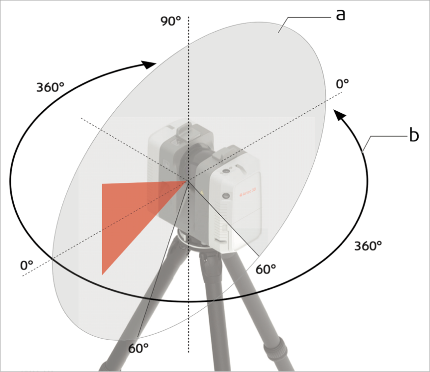
Figure 19 Ray II - Field of view visualization where a represents the vertical field of view: 300° and b represents the horizontal field of view: 360°
Scan Settings
To adjust scan settings, click the Settings icon to open the Settings screen.
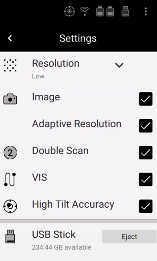
Figure 20 Ray II - Settings screen.
Resolution:
Low: 12 mm @ 10 m, maximum range 130 m
Medium: 6 mm @ 10 m, maximum range 130 m
High: 3 mm @ 10 m, maximum range 65 m
Image enables High dynamic range (HDR) image
Adaptive Resolution enables adaptive image resolution. Image resolution gets automatically adapted to suit the selected scan resolution.
Note
By default, the setting is disabled. To get images with highest resolution for all kinds of scan resol- utions keep the setting disabled.
Double Scan enable the Double Scan which automatically removes moving objects.
VIS enables Visual inertial system. Video enhanced inertial measuring system to track movement of the scanner position relative to the previous setup in real time.
High Tilt Accuracy. To achieve the specified high tilt accuracy, the approximate GPS position of the scanner must be known.
Note
High Tilt Accuracy is applied only when the scanner is positioned inside the working range of the High Tilt Accuracy mode. This is indicated by the icon in the status field of the display and by the LED indicator. It is recommended to leave the GPS setting enabled so that the scanner’s position is automatically updated. Make sure that the GPS position is updated after travelling with the scanner a long distance (> 100 km) before starting a project in a new location. The scanner’s GPS position can be updated manually by tapping the Update button.
For more general settings with a detailed description, please refer to the full version of the User Manual (3.5.3 Settings).
Scanning screen
The Start screen is displayed after the system boot process. Once it is visible the scanner is ready for work.
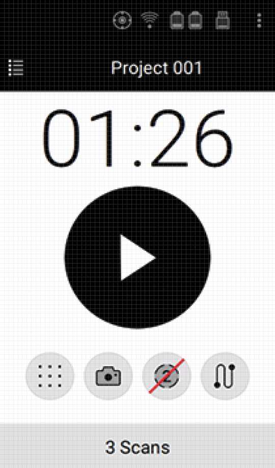
Figure 21 Ray II - Start screen.
Element |
Icon |
Details |
|---|---|---|
|
Project not signed |
|
|
Project signed |
|
|
Project signed, but modified |
|
|
High tilt accuracy mode enabled. Scanner is leveled within ±10° in upright or upside down orientation. High tilt accuracy of 18’’ is applied. |
|
|
High Tilt Accuracy mode enabled. Scanner is tilted more than ±10° in upright or upside down orientation. High tilt accuracy of 18’’ is not applied. |
|
|
WLAN enabled |
|
|
0% - 25% of storage used. For other batteried stated, please refer to the “Scanning” section in the full version of this manual (About This Manual). |
|
|
Click the Settings icon to open the Settings screen. |
|
|
Click the Project icon to open a list of all stored projects. |
|
|
Display of the acquisition time depending on the scan settings |
|
|
Click the Start button to start the scan and image acquisition as defined in the scan settings. |
|
|
For all scan settings, please refer to Scan Settings |
Scanning
To control the process of scanning and see the result, you can use the mobile Artec Remote application. Please refer to the Software installation section.
To scan with an Artec Ray II, follow these steps:
Ensure the Artec Ray II is turned on, with the USB cable unplugged.
Open the Artec Remote app on your phone or device; and connect to the Artec Ray II via Wi-Fi.
Tap the Go to Scan button. The list of your projects will open. If there are no projects yet, the list will be empty.
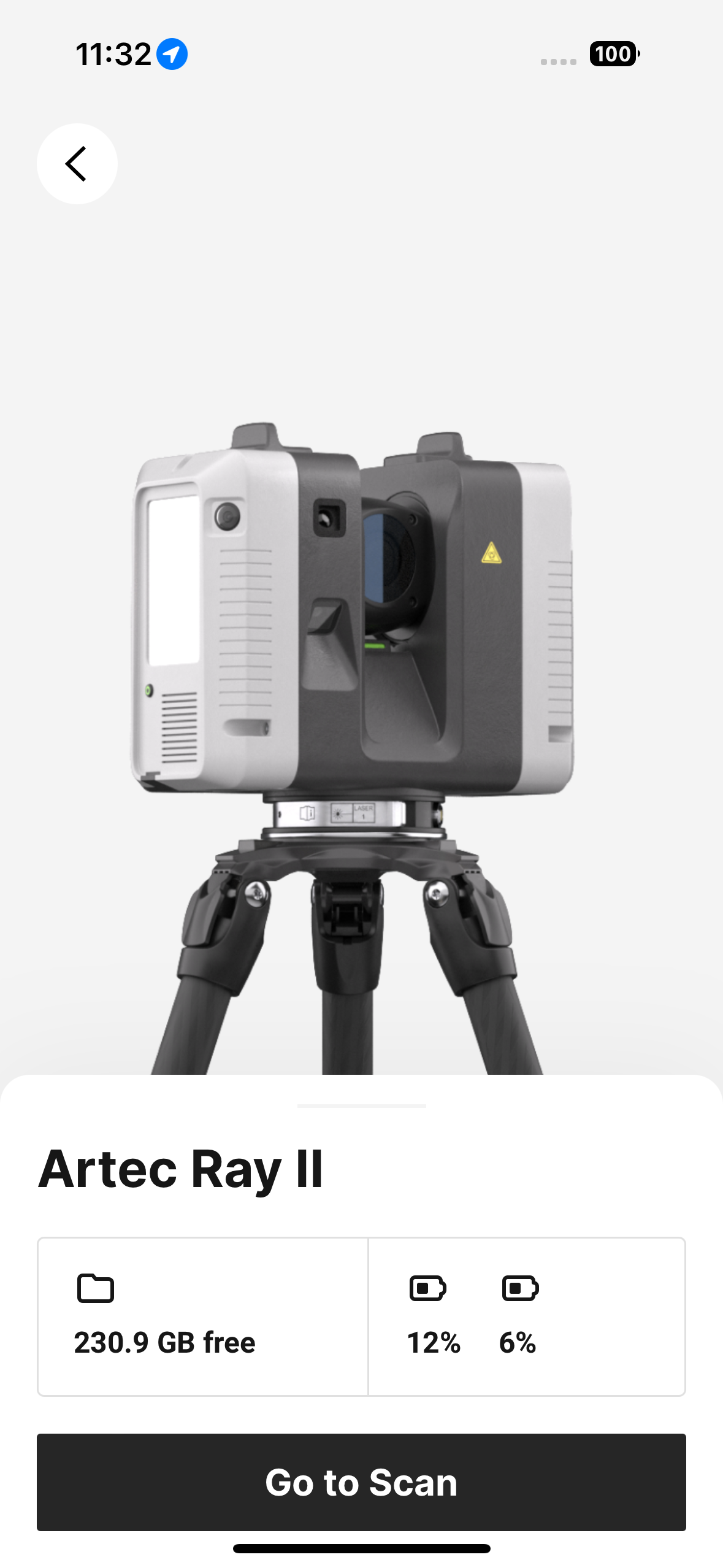
Figure 22 Go to Scan screen
Tap the New project button to start a new project, or select the existing one.
Adjust scanning settings as needed by dragging the Scan bottom sheet up. Depending on the chosen settings, scanning time may vary.
Click the play button with the estimated time label to start scanning.

Figure 23 Play button to start scanning
Once preparing and scanning processes are complete, you will see an image of your scanned object.
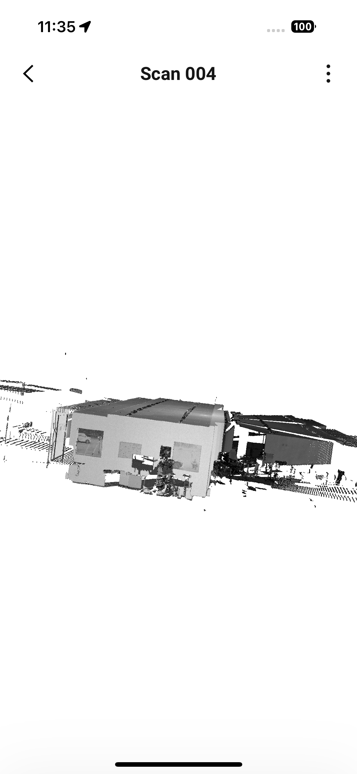
Figure 24 Scanned object
Note
It is possible to get back to your project at any time later and add some more scans if needed.
To scan with an Artec Ray II, follow these steps:
Ensure the Artec Ray II is turned on, with the USB cable unplugged.
Open the Artec Remote app on your phone or device; and connect to the Artec Ray II via Wi-Fi.
Tap the Go to Scan button. The list of your projects will open. If there are no projects yet, the list will be empty.
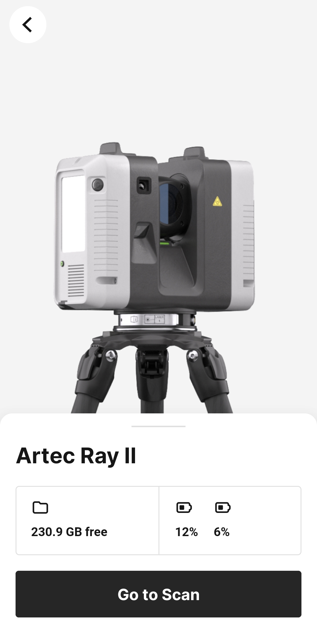
Figure 25 Go to Scan screen
Tap the New project button to start a new project, or select the existing one.
Adjust scanning settings as needed by dragging the Scan bottom sheet up. Depending on the chosen settings, scanning time may vary.
Click the play button with the estimated time label to start scanning.

Figure 26 Play button to start scanning
Once preparing and scanning processes are complete, you will see an image of your scanned object.
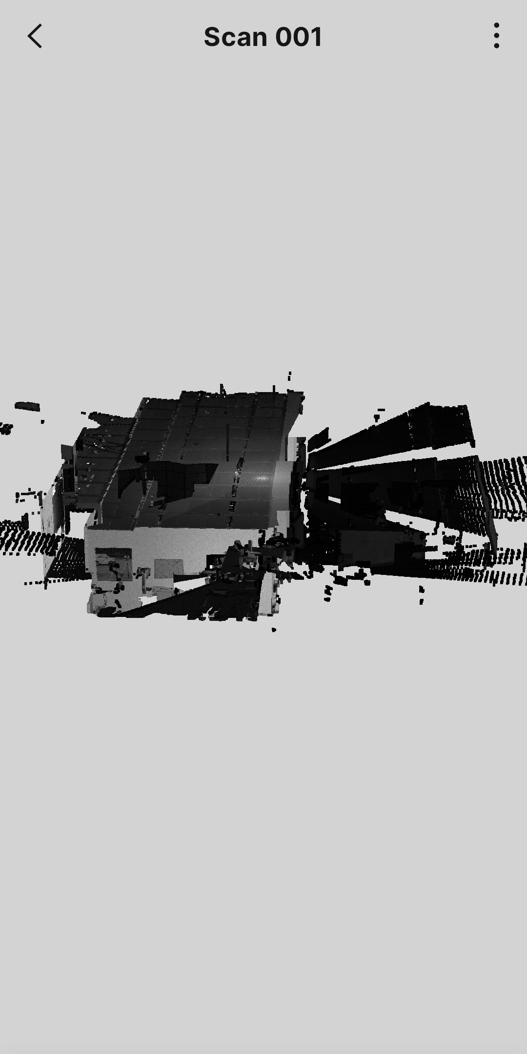
Figure 27 Scanned object
Note
It is possible to get back to your project at any time later and add some more scans if needed.
Troubleshooting
If you encounter any troubles while scanning you can check Troubleshooting solutions below. Otherwise, please e-mail the scanner’s log files to Artec3D Support Team at support@artec3d.com.
Note
Log files can be transferred to the USB stick using the Transfer command in the Settings screen.
Problem |
Possible Cause(s) |
Suggested Remedies |
|---|---|---|
|
Capacity of battery is too low. |
Recharge or change battery. |
|
Battery charger is defective or exchangeable battery is no longer charging. |
If battery charger is defective, check the function of the battery charger. Please note the charging status displayed on the battery charger. If battery is no longer charging, try replacing it. |
|
Dust, debris or fingerprints on the rotating mirror-protection glass |
Use a glass cleaning tissue to clean the specific areas. |


