Scanning with Micro
Open Micro Scan Panel
- Launch Artec Studio.
- Open Scan panel.
- Click Scan with Artec Micro.
Calibrate Scanner
Before starting, you must calibrate your Micro. Also consider recalibrating the machine if you move it or leave it unused for a long period.
|
|
|
 |
|
|
|
 |
|
|
|
|
|
Prepare Objects
You can affix an object using either of the jigs or special adhesive putty. The maximum object height is 9 cm (3.5 in).
Black, transparent and reflective surfaces need dusting with anti-glare spray.
Warning
Apply spray before mounting objects.
Perform Scan
To make a scan, perform the steps:
|
The object must be entirely visible. For large objects, consider removing extra spacers from the scanner. When affixing small objects, be sure to use all spacers to position the object as close to the camera as possible. |
|
Tune it to minimize areas highlighted in red (potentially noisy areas). |
|
For simple cases, use Preview. If your computer has an Nvidia graphics card, opt for Automatic path. |
|
Micro will start capturing frame while swinging the L-shaped arm and rotating the turntable. |
|
Use the left-mouse button to rotate and the scroll wheel to zoom. |
|
Orient object in 3D view and then click this button. |
If necessary, flip the object and affix it again. Then repeat the steps above to scan the remaining areas. You’ll need to later align the scans obtained this way.
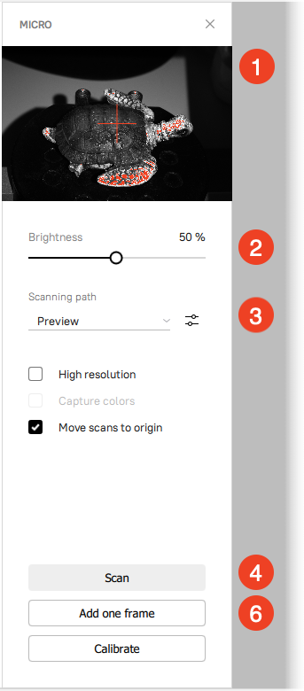
Framing and Quality Options
The Micro black-and-white camera provides a real-time preview (see the image above, ➊). Use the image from the camera to orient the object correctly. Ensure the following:
- Preview area fits the entire object.
- The cross mark appears in the middle of the object.
Use the following options to improve the quality of the resulting 3D model and to capture the texture of the object:
| Brightness | Brightness is the scanner’s reconstruction capability. First, increase it to make the object visible in the preview. Next, tune it to minimize areas highlighted in red (potentially noisy areas). |
| High resolution | Yields scans of ultra-high quality (12 times more polygons). Select this checkbox if you plan to resolve details up to 15 microns or capture colors. |
| Capture colors | Defines whether to record texture. This option is available only in High resolution mode and increases scan time. |
| Move scans to the origin | Positions the scans in the coordinate origin. The possible drawback is that the scans might be slightly misaligned. |
Automatic Scanning
Micro can create a path automatically by analyzing the affixed object and ensuring sufficient surface coverage with a minimum of frames.
Note
To start Automatic path, your computer needs to have an Nvidia graphics card with at least 2 GB of memory and a CUDA compute capability of at least 3.5.
- Adjust Brightness as necessary.
- Select the Automatic path from the Scanning path dropdown list.
- Wait for the scanner to finish capturing. It usually captures 20 frames.
- Examine the scan and add one frame as necessary.
- Flip the object, affix it, select the Auto-align new scans with those marked in Workspace checkbox and repeat these steps again.
Auto-Alignment
When creating each new scan using the Automatic path, you can benefit from the auto-alignment.
- Ensure the previously made scans are selected in Workspace.
- Select the Auto-align new scans with those marked in Workspace checkbox.
- Use the Frames used for alignment slider to define the number of frames from the selected scans to be employed during alignment. The more the frames, the more reliable the results, but the slower the process.
Scanning Paths
Scanning path is a set of turntable positions relative to the camera due to the scanner’s rotary mechanisms.

Figure 1 L-shaped arm’s swing and turntable’s rotation.
There are two main parameters that affect the number of these positions and the number of frames:
- Object’s size
- Geometry complexity
Default Paths
Artec Studio provides the set of the predefined scanning paths. Click the Scanning path drop-down list and select a suitable item from the Default paths nested list.
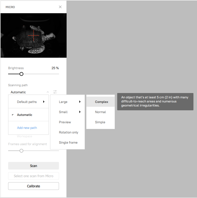
Figure 2 Default scanning paths.
The tables below provide a description of the default paths.
| Size- and complexity-based paths | |
|---|---|
| Small → Simple | An object no bigger than 5 cm with no difficult-to-reach areas and few or no geometrical irregularities |
| Small → Normal | An object no bigger than 5 cm with few difficult-to-reach areas and some geometrical irregularities |
| Small → Complex | An object no bigger than 5 cm with many difficult-to-reach areas and numerous geometrical irregularities |
| Large → Simple | An object that’s at least 5 cm with no difficult-to-reach areas and few or no geometrical irregularities |
| Large → Normal | An object that’s at least 5 cm with few difficult-to-reach areas and some geometrical irregularities |
| Large → Complex | An object that’s at least 5 cm with many difficult-to-reach areas and numerous geometrical irregularities |
| Additional paths | |
|---|---|
| Preview | A quick preview from six different angles. Use to check how well the object surface can be scanned or how many scanning angles it requires. |
| Single frame | Capture just one frame without rotating the turntable. Use this mode to cover blind spots from other trajectories—simply rotate the object to face the camera. |
| Rotation only | Objects that are ring shaped or that can’t be properly affixed to the turntable can fall off when the arm swings. This path instructs Micro to rotate the turntable only, without tilting the arm (see Figure 1). |
Adding One Frame
After scanning an object, you may need to add separate frames from certain angles to fill in unscanned areas.
To add a frame into the existing Micro scan captured using either of the paths, follow the steps:
- In the 3D view window, orient the object in the way the unscanned area is facing your view direction.
- Click Add one frame.
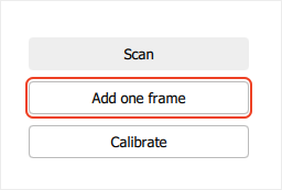
Figure 3 Adding one frame.
If the current scan orientation doesn’t allow adding a frame, this button will be grayed out. To resolve this issue, try reorienting the scan in the 3D view window.
Creating New Path
You can create a custom scanning path if the default paths aren’t optimal for the object. For this purpose, the Scanning path drop-down list contains the Add new path item.
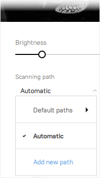
Figure 4 Add new path.
After selecting Add new path, the path editor will open.
By clicking to the right of the step row, via the pop-up menu you can delete, duplicate steps, and create a path sequence.
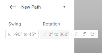
Figure 5 Creating new path.
Each step defines a position of the turntable relative to the Micro cameras using two parameters:
- Swing defines an angle of the turntable tilt. The value is in range of -90° to 45°. The default value is 0°, which means there will be no tilt of the turntable.
- Rotation defines a rotation angle of the turntable (clockwise). The value is in range of 0° to 360°. The default value is 0°, which means that the turntable will not rotate.

Thus, by setting rotation angles in each tilt position, you create a new scanning path.
Creating Path Manually
Adding a new path manually is reduced to a combination of the following operations:
- Filling in the parameters of a certain step.
- Duplication of the step and editing of the created one.
- Removing unnecessary steps.
All these operations are performed using the pop-up menu described above.
After you have created the necessary steps, click Save. Your path will now be available in the Scanning path → My paths list.
Creating a Path Sequence
Artec Studio provides the ability to automatically generate a scanning path by setting only key parameters of a path sequence.
Click Add new path in the Scanning path drop-down list. Then, click to the right of the step row and select Create sequence from a pop-up menu.
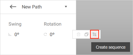
Figure 6 Creating the sequence.
The following parameters must be set to generate the path sequence:
- Swing start angle is the largest inward tilt of the turntable.
- Swing end angle is the largest outward tilt of the turntable.
- Swing interval controls the amount of the tilt positions.
- Rotation interval controls how many turns the turntable will make in each tilt position.
Once all parameters have been set, Artec Studio will automatically count how many positions and frames the sequence will create.
Caution
If you set the intervals too short, Artec Studio will inform you that the frame count is exceeded (see figure below).
Click the Generate button to get back to the path editing menu with the generated path.

Figure 7 Generating the sequence.
If the automatically generated path sequence satisfies you, click Save and now your custom path will be available through the Scanning path → My paths nested list.
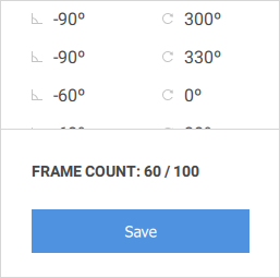
Figure 8 Save the sequence.
Note
It is possible to add a subsequence to an existing sequence, for example with the specific rotation interval for a certain tilt position. Select the desired step in the sequence, click to the right of the step row and select “Create sequence”. Perform the same operations to create the sequence as described above.
Any step from the sequence can be edited manually, which allows to create a perfect scanning path for a specific object.
Editing Paths
Each custom path can be edited via button ![]() .
.
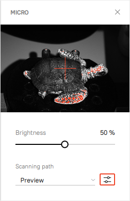
Figure 9 The edit ![]() button.
button.
Next, you can do any available operations on the paths as described above. Also note the drop-down list at the top right of the path editor, which allows you to save, duplicate, rename and delete the path.
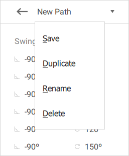
Figure 10 Operations with the path.
You can also use button ![]() with the default paths. You can’t edit them directly, but you can create your custom paths based on them. Use the Duplicate item in the drop-down list as shown below:
with the default paths. You can’t edit them directly, but you can create your custom paths based on them. Use the Duplicate item in the drop-down list as shown below:
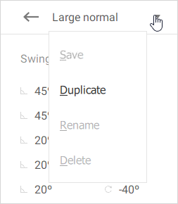
Figure 11 Duplicating the default (Large normal) path.
Custom Scanning Path Tips
Tip
When using Micro, try scanning all object’s surfaces with the fewest possible frames.
Tip
Creating a perfect custom path is only reasonable for those object types which will be scanned multiple times.
Important
Two scanning sessions with object’s flipping using a moderate path (in terms of positions) might be better than a single session using a complex path. This approach is likely to yield fewer frames and unscanned areas.
Tip
The real turntable movements may not follow the order in the sequence. Artec Studio always optimizes this order in terms of scanning time and instructs Micro accordingly.
Angles
When scanning with two spacers and a negative tilt angle, the jig may often obstruct an object and prevent the scanning.
The ball on the photo below is obstructed and will not be scanned from this angle (note the jig’s shadow).
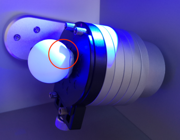
Figure 12 The obstructed ball.
Regardless of the object type and the way it was attached to the turntable, the bottom part will always be inaccessible to Micro, so you need to flip the object and make a second scan after the first one.
Some objects require the second scan to be complete, or even require more than two scans from different sides. But if the object is simple, the second scan can be done using the Preview or Single Frame default scanning path.