Using the Hardware
3D Scanners
Artec Studio can work with one or more Artec 3D scanners. It offers tools to quickly create 3D models of physical objects. Besides managing the process of capturing objects, it lets you perform full data postprocessing, optimize mesh tessellations and apply other operations to obtain a quality 3D model. You can then send the complete model to a CNC machine or import it to another 3D-modeling application.
Most Artec 3D scanners are specifically designed for handheld use, offering light weight and compact size. Using them is easy—no special knowledge or skills are necessary. To obtain a complete 3D model, simply scan the object from different angles and fuse the resulting scans into a single model using Artec Studio.
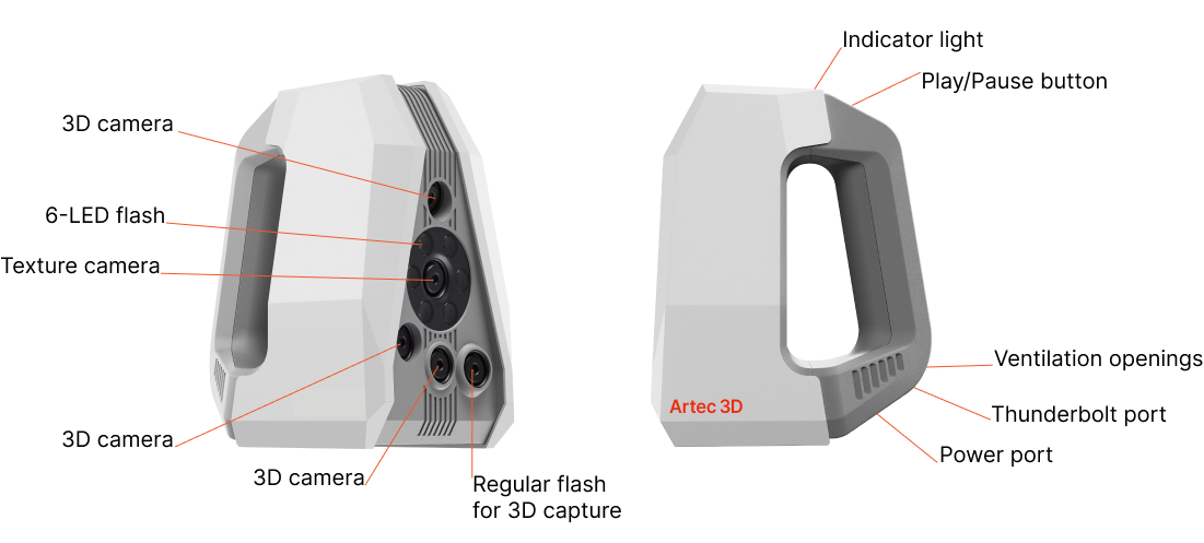
Figure 21 Spider II components.
For detailed information on the technical specifications of Artec Spider II, scanning settings, and the full scanning workflow, refer to the Artec Spider II User Manual . For a quick start guide and safety instructions, see the Artec Spider II Quick Start Guide .
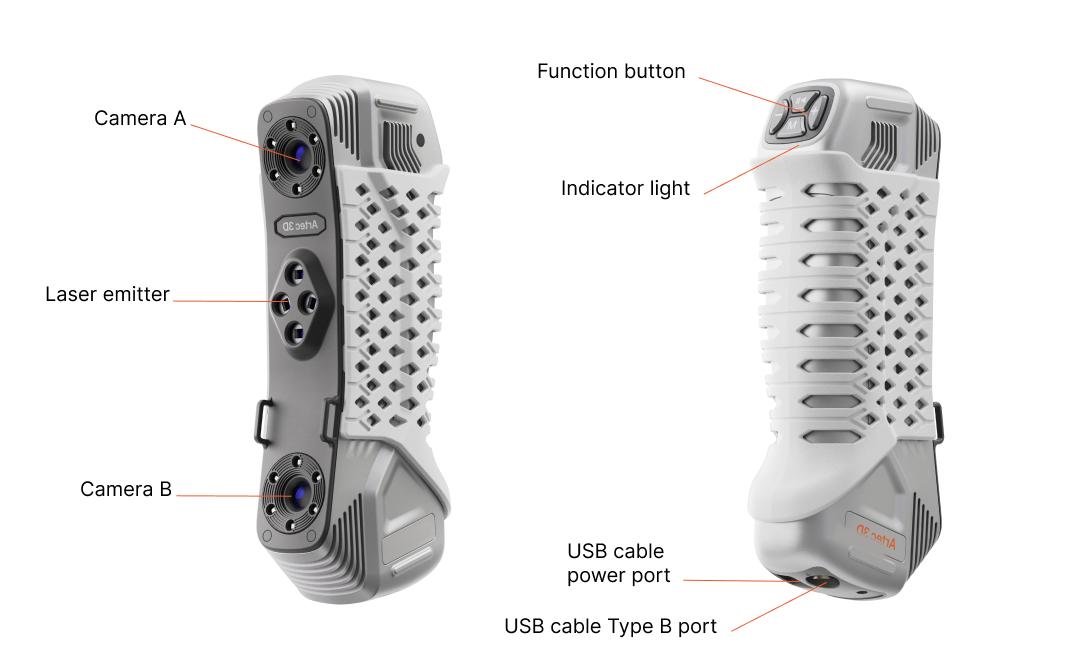
Figure 22 Point components.
For detailed information on the technical specifications of Artec Point, scanning settings, and the full scanning workflow, refer to the Artec Point User Manual . For a quick start guide and safety instructions, see the Artec Point Quick Start Guide .
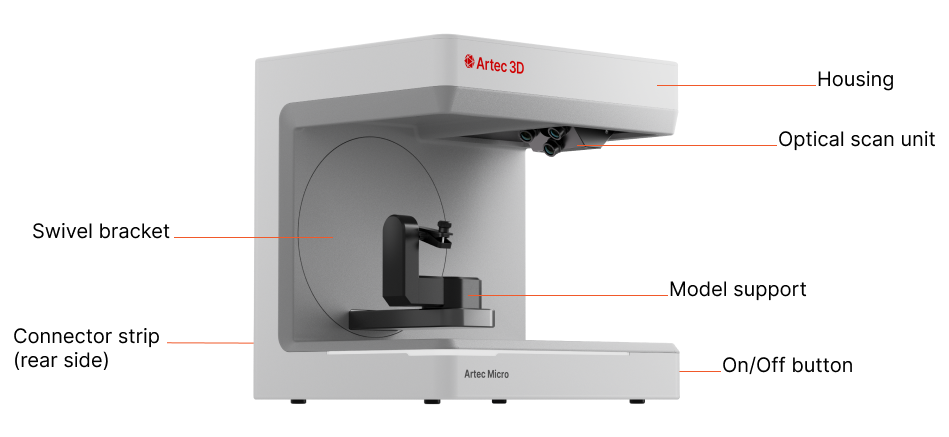
Figure 23 Micro II components.
For detailed information on the technical specifications of Artec Micro II, scanning settings, and the full scanning workflow, refer to the Artec Micro II User Manual . For a quick start guide and safety instructions, see the Artec Micro II Quick Start Guide .
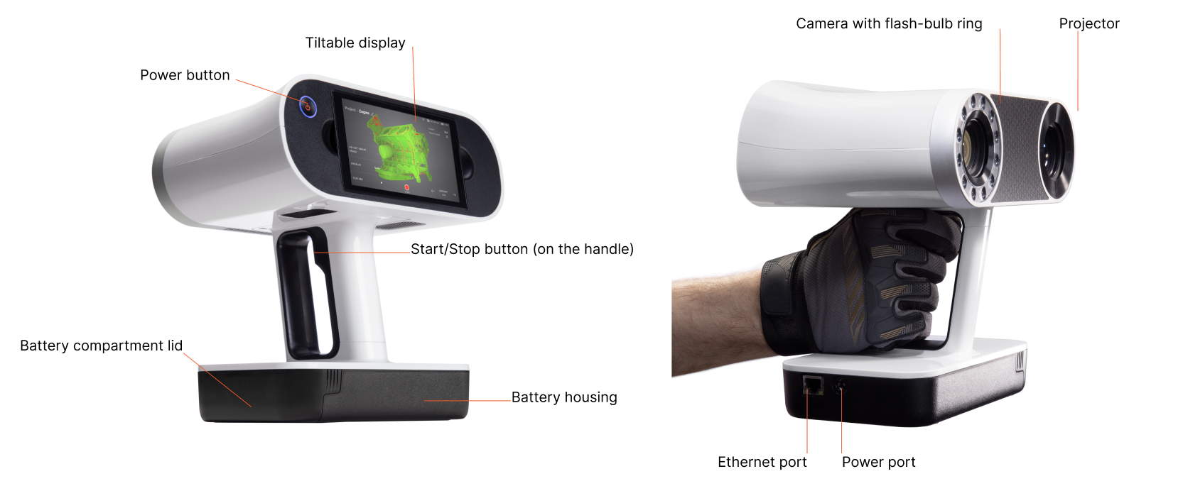
Figure 24 Leo components.
For detailed information on the technical specifications of Artec Leo, scanning settings, and the full scanning workflow, refer to the Artec Leo web manual . For a quick start guide and safety instructions, see the Artec Leo Quick Start Guide .
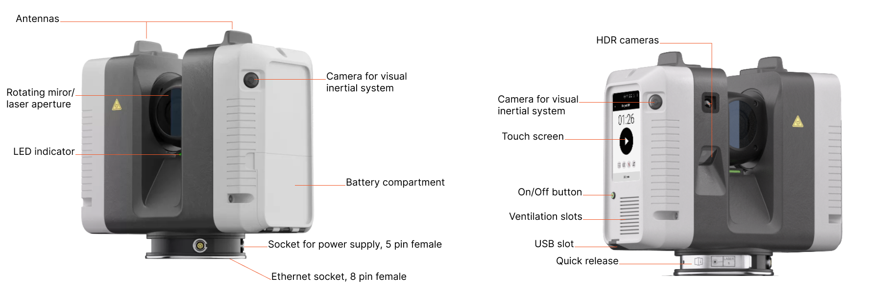
Figure 25 Ray II components.
For detailed information on the technical specifications of Artec Ray II, scanning settings, and the full scanning workflow, refer to the Artec Ray II User Manual . This user manual is available in multiple languages on Documentation Portal. For a quick start guide and safety instructions, see the Artec Ray II Quick Start Guide .
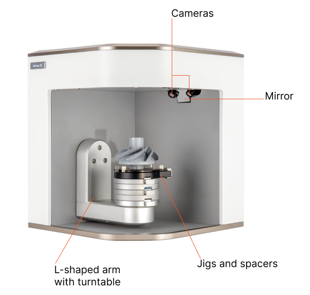
Figure 26 Micro components.
For detailed information on the technical specifications of Artec Micro, scanning settings, and the full scanning workflow, refer to the Artec Micro web manual . For a quick start guide and safety instructions, see the Artec Micro Quick Start Guide .
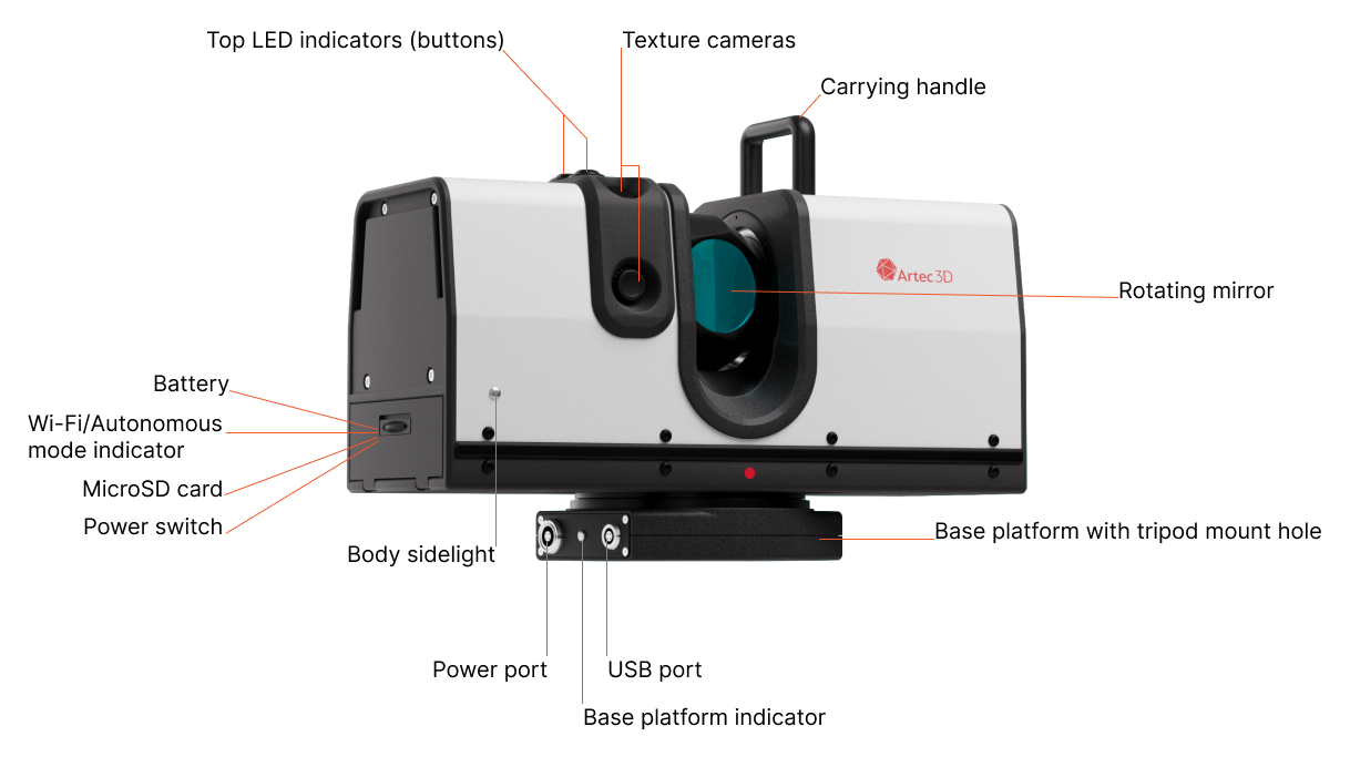
Figure 27 Ray components.
For detailed information on the technical specifications of Artec Ray, scanning settings, and the full scanning workflow, refer to the Artec Ray web manual .
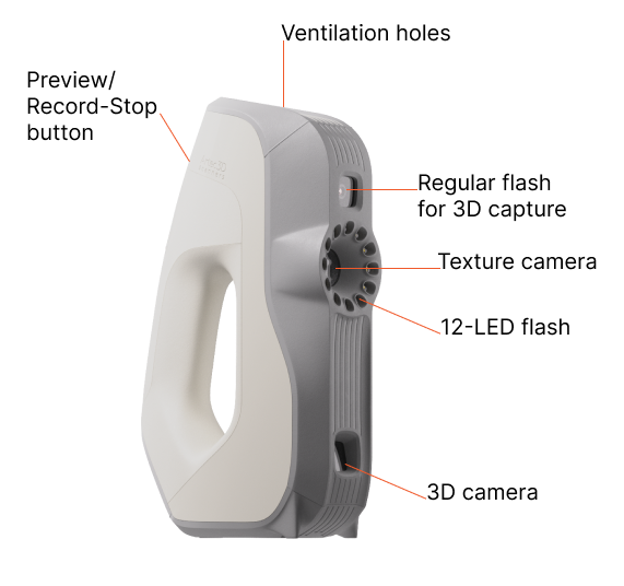
Figure 28 Eva components.
For detailed information on scanning with multiple Eva scanners, refer to Hardware Synchronization for Eva , for HD scanning with Eva, see Notes on HD Scanning With Eva, and for further processing of scanned data, visit the Data Processing page.
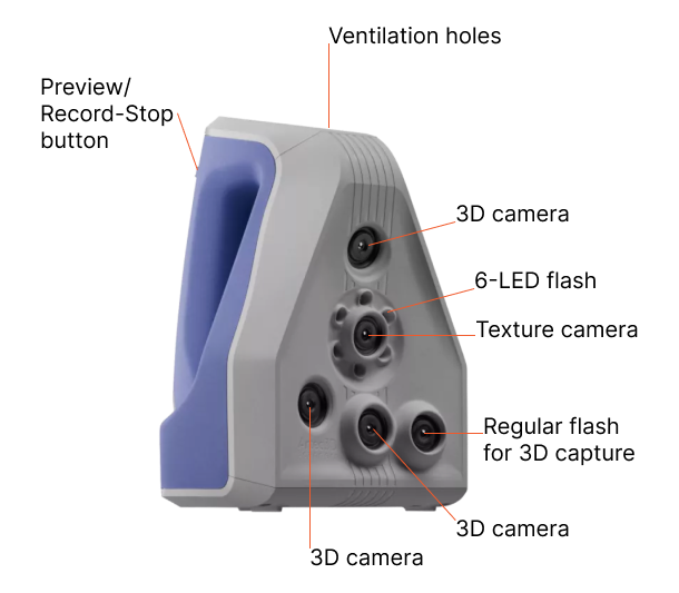
Figure 29 Spider components.
For detailed information on scanning workflow, refer to Notes on Scanning With Spider and for further processing of scanned data, visit the Data Processing page.
Field of View Comparison: Artec Eva vs. Artec Spider
Depending on the size of the object you’re scanning, use either the Artec Point, Artec Ray/Ray II, Leo, Eva, Spider/Spider II, or Micro/Micro II. The primary difference between these models is the depth and field of view. They also differ in 3D resolution as well as point accuracy; consult the Artec website and relevant manuals for details.
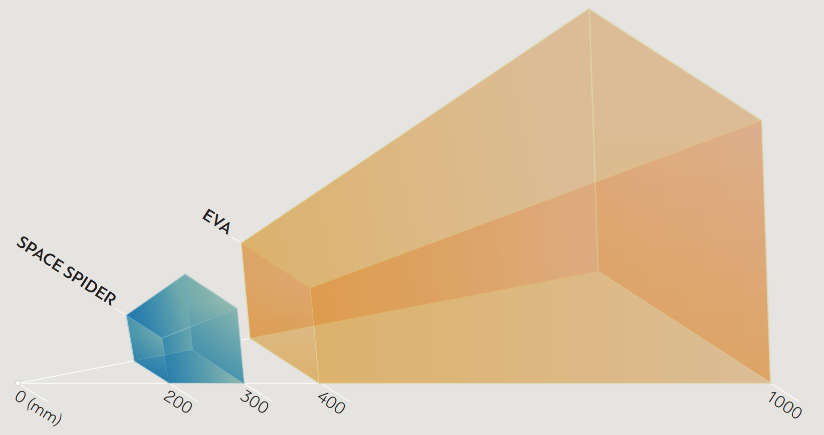
Figure 39 Fields of view for Eva and Spider 3D scanners.
You can combine several different scanner types while capturing a scene. In some cases when capturing complex shapes, this capability increases the scanning rate and enables you to achieve your desired precision.
LED Indicators for Eva, Spider and Spider II
Artec scanners include built-in multicolor indicators. By explaining the meaning of these indicators, the list below enables you to keep track of the scanning process:

Steady blue—scanner is booting up.

Flashing green—Artec Studio cannot detect a 3D scanner.

Steady green—scanner is connected to the application and ready to use.

Flashing red—scanner is in Preview mode, or tracking in Recording mode is lost.

Steady red—scanner is in Recording mode and object tracking is proceeding correctly.
Hardware Buttons for Eva, Spider and Spider II
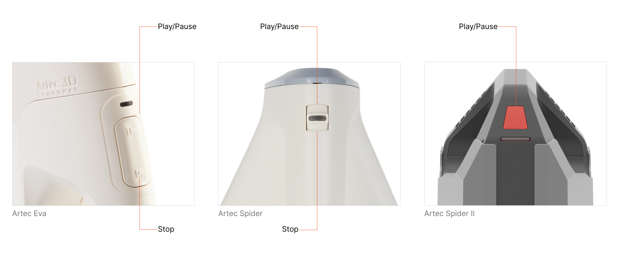
Figure 40 Scanner buttons: Artec Spider on the left and Artec Eva on the right.
Artec Eva and Artec Spider scanners have three-position buttons on their bodies.

—press this button once to open the Scan panel and start Preview mode; press it once more to switch to Recording mode. Subsequently, pressing this button will switch between Preview and Recording.

—press once during a scan to stop the scanning process; press twice to stop scanning and close the Scan panel.
Artec Spider II scanner has a Play/Pause red button on its body.
—Being in the open Scan panel, click the Preview button, direct the scanner at the object, then press the Play/Pause button on the scanner to switch from Preview to Recording mode. To pause scanning, press this button once more. To complete scanning, click the Stop button in the Scan panel.
Hardware Synchronization for Eva
Artec Eva is equipped with two jacks designed for 6P6C connectors (RJ12). By creating a bundle, you can link multiple Artec Eva scanners to each other. The master device is a leading scanner that sends signals to the next slave device. Each subsequent device is connected to the previous one sequentially as Figure 41 shows. To connect the devices, you can use a standard phone cable (RJ12 6P6C) or any other cable that uses the conductor scheme shown in Figure 41. Each scanner should also connect to the PC via USB.
Warning
Only Artec Eva scanners can connect to each other. Do not connect Artec Eva to a telephone wall port!
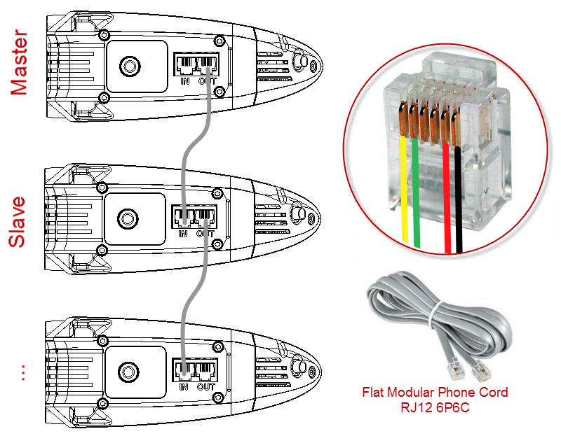
Figure 41 Synchronization scheme.
Jacks on the Artec Eva scanner shown at left and conductors in a 6P6C connector shown at right.
Artec Turntable
Artec Turntable is designed to ease scanning of small and midsize objects by eliminating the need to rotate them manually. Both the rotary plate and the mat that comes with the turntable feature a special pattern to ensure robust tracking with Artec scanners. The mat is made of silicone, which prevents objects from sliding off the rotary plate.
To become familiar with the turntable, download Quick Start Guide.
To scan using Turntable, follow the steps:
Ensure your computer has a Bluetooth adapter that supports the 4.0 standard.
Add a new Bluetooth device.
Open Artec Studio.
Access the Scan panel.
Select the Use turntable checkbox.
Place the object on the turntable.
Click Preview.
Click Record to start capturing. The turntable will start rotating.
Click Pause or Stop. The turntable will stop rotating.
Recovering Lost Tracking
If you experience a tracking loss, Artec Studio will pause the turntable. It also turns the rotary plate back by about 15 degrees. Once the application has recovered tracking, it resumes rotation.
3D Mouse
Artec Studio can work with 3Dconnexion manipulators.
Basic support includes navigation in 3D View and the following commands:
Home
Fit to view
Undo
Redo
For 3D mouse to function, you need to install drivers from the manufacturer’s website. Additionally, you can assign four currently supported commands to the mouse radial menu or at least two of them to the hardware buttons for Artec Studio.
To assign a command to the 3D mouse button, follow the steps:
Open Artec Studio
Then open 3Dconnexion Properties utility from the Windows tray
Click Buttons
Click on the > arrow on the right side of either button field. A flyout window will open for that 3D mouse button.
Open the Artec Studio category
Select either of the currently supported command.
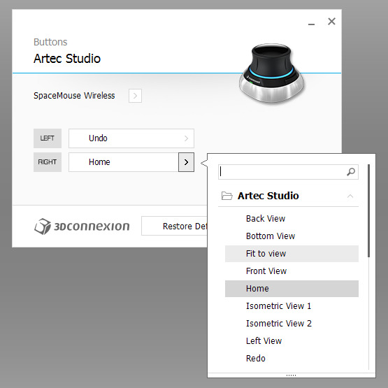
Figure 42 Assigning command to 3D mouse button.
If you want to assign several commands, create a new Radial menu (use the eponymous category in the flyout menu). For more information, consult the manual for your 3Dconnexion mouse.
To get used to navigating 3D content, use 3Dconnexion Trainer or 3Dconnexion Demo from the 3Dxonnextion Home application.
Note
In Artec Studio, you move the camera around the object rather than the object itself.
Artec Battery Pack
Available as an accessory, battery pack allows you to scan anywhere without the need to be near a power outlet. Battery from this pack supports Artec Eva, Artec Spider and Artec MHT scanners and lasts for up to 6 hours of scanning.
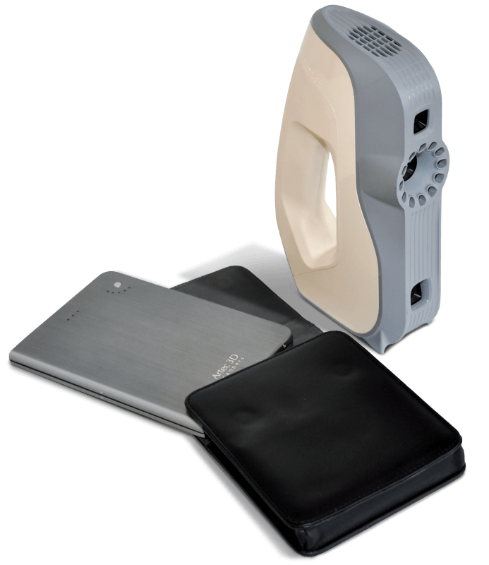
Figure 43 Battery pack with Eva.
Battery pack includes the following items:
Battery
Battery pouch
Power adapter (110–230 V → 19 V)
Fully charge Artec battery using its Input socket.
Plug the cable into the battery Output socket.
Then connect the cable to your Artec scanner.
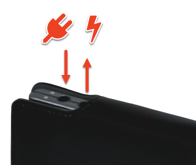
Figure 44 Battery ports from left to right: Input, Output.
Important
Never confuse battery ports when connecting scanner.