Scanning
Understanding Application
Color Prompter
ScanApp™ features the Color prompter which measures a distance to the surface being scanned and render it based on the distance measured (Fig. 3). As the specs say, EVA’s working distance falls in the range from 0.4 to 1 meter.
| Green: | indicates that you are holding your scanner at the optimal distance from the object (approximately 0.7 meter) |
|---|---|
| Orange–red: | tells you that your scanner is too close to the object |
| Blue: | marks surfaces that are too far from your scanner |
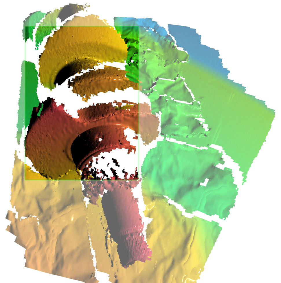
Fig. 3 Color prompter in ScanApp™.
Note
Yon can disable Color Prompter in the View Menu. In this case, ScanApp™ will render texture.
Selecting and Preparing Objects for Scanning
Operation of Artec 3D scanners is based on the structured-light 3D reconstruction method. Since the method of capturing 3D frames is optical, certain types of objects are difficult to scan. Certain techniques, however, enable successful processing of such objects. For example, you can cover a transparent or dark object with a light paint or dust it with talcum powder. You can also use other easily removable substances or a special anti-glare spray.
Technique
- Pay closer attention to the screen and the Scanning viewport [1] than to the actual object.
- Don’t move the scanner too fast
- Always keep in Scanning viewport [1] the sufficient part the object
- Keep the object in the Green or Yellow zone of the Color prompter
- If you’re scanning an object over several scans, remember to scan a common area in both scans to ensure the successful alignment
- If you’re scanning an object over one scan, either way, capture the object all the way around, plus a little more (360+ degrees)
- Avoid capturing any object that may change shape during the scanning process. When the geometry of the scene is changing, the system may fail to find the correct position of new frames relative to previously aligned ones.
- Don’t record excessive number of frames: ensure that all regions are sufficiently scanned, but don’t scan them twice, except when providing common areas for subsequent alignment.
| [1] | (1, 2, 3) Scanning viewport is a rectangle in the 3D View window showing the scanner’s field of view in a current moment. The outer regions are rendered using faded colors. |
Scanning
Once you’re all set with Installation, you can start scanning.
- To start and pause scanning, you can also press
 on the scanner body
 - Once you click Pause, the recording suspends and the scanned scene pulls back, and the Color prompter stops rendering colors.
- When you resume scanning after pausing, ScanApp™ stores new frames in the same scan. Whereas starting after Stop creates a new scan.
To start capture,
- Ensure that scanner is connected (the led indicator on the scanner body is steady green
 and the
  icon is displayed in the application window)
 - Click Start New Scanning, the scanner will activate the preview mode
- Direct the scanner at the object and familiarize yourself with the color rendering scheme (see Color Prompter)
- Ensure that surfaces in the Scanning viewport [1] are rendered in green (Fig. 4)
- Click Capture (or press ) to start recording 3D data
- Gradually move the scanner while monitoring the process in the 3D View window
- Capture what you can and pause the session by clicking the Pause button
- Turn the object or prepare it otherwise and capture an already scanned area and then any remaining unscanned regions
- Once you have successfully captured the object from all sides, click the Stop button or press
 .
.
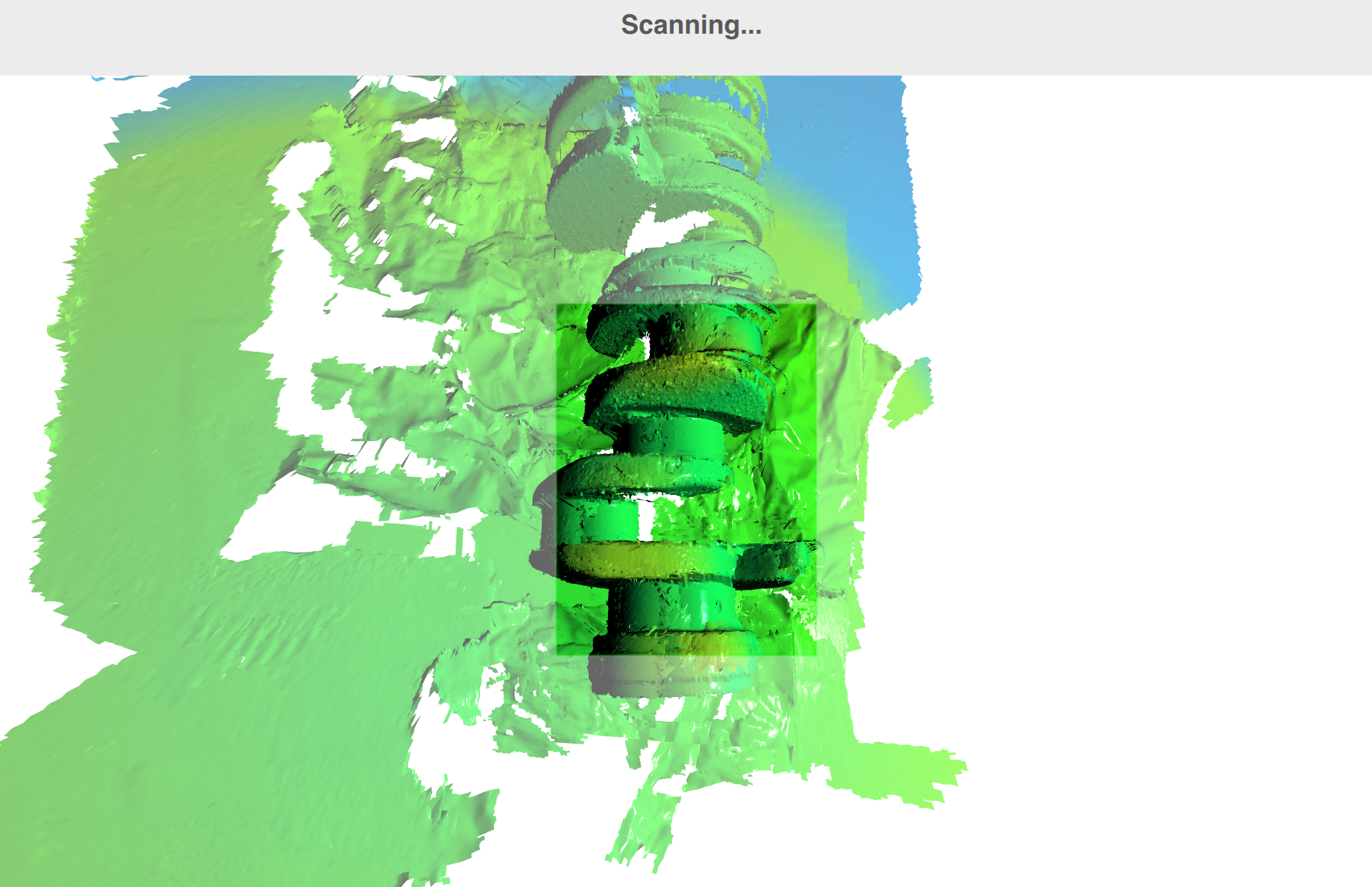
Fig. 4 3D View window during scanning (Scanning viewport in the middle)