Workspace and More
Artec Studio User Interface
Windows, Panels and Bars
When you launch Artec Studio, you will see the main application window, which allows you to perform all operations on scans and models.
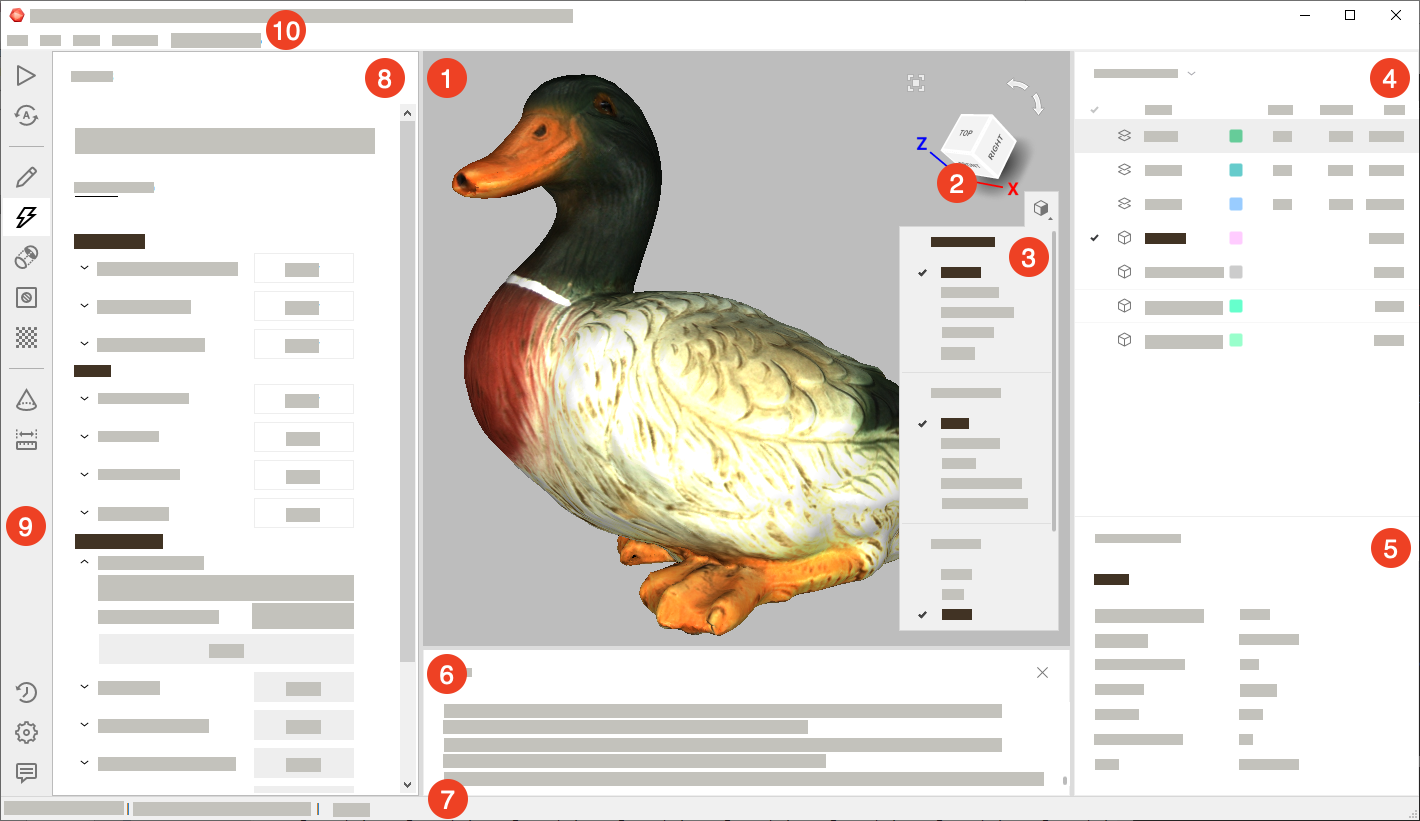
The main window is divided into several sections:
| Section | Intent and other information |
|---|---|
|
Display all 3D data. |
|
Quickly orient objects. |
|
Alter 3D-data appearance and toggle display of coordinate grid. |
|
List and manage 3D objects as well as toggle their display and availability for tools. |
|
Display detailed information for 3D objects. |
|
Store records of any executed commands, specifying the time and details of each operation (error and troubleshooting messages). |
|
Contains information on memory availability and current usage by Artec Studio. It also has a progress indicator for any currently running task, such as algorithm execution, model and scan exporting, and so on. |
|
Accommodate panels for various application modes, including Scan, Autopilot, Editor, Tools, Align, Fix holes, Texture, Construct, Measures, Settings, History and Feedback |
|
Toolbar to start the above mentioned modes. |
|
Dropdown menus with various commands. |
If either of the panels is hidden, use the File → Window menu command to show it.
You can also quickly show or hide some of the panels/toolbars (namely, Left toolbar, Workspace panel and Log window) by clicking on the special bars marked with double arrows: ![]() ,
, ![]() ,
, ![]() ,
, ![]() . These bars are located along one of the borders of the corresponding panel or toolbar.
. These bars are located along one of the borders of the corresponding panel or toolbar.
Primary Settings
To access the settings dialog, select Settings… in the File menu. The settings window has several tabs for various groups of application settings. To switch between the tabs, click the icon at the top of the dialog. For a detailed description of the tabs, see Settings.
To change the language, select the Miscellaneous tab (Figure 157) and then the required language from the list and click OK. You will be asked to confirm the operation and restart the application. Once you agree, Artec Studio will automatically restart using the new interface language. If you choose not to restart, the changes will be applied the next time you start the application.
Under the Performance tab you can specify the maximum number of alterations to be saved, or specify maximum the size (in MB) of the history to be saved. The Data-compression level slider enables you to adjust the compression level when saving project data to a disk.
Workspace Panel
Object Types
After each scanning iteration, Artec Studio saves a separate scan. The list of all scans for a given project appears in the Workspace panel (see Figure 61). Afterwards, the algorithms, primarily fusion, yield models.
Artec Studio can accommodate the following types of objects in Workspace:
| Type | Icon | Content | Origin |
|---|---|---|---|
| Scan |  |
Set of frames | From scanners Eva, Spider, Leo, and Micro |
| Point-cloud scan |  |
Point cloud | From Ray scanner |
| Model |  |
Polygonal mesh | Algorithm output (fusion) or imported mesh |
| CAD model |  |
CAD model | Imported |
| Cylinder |  |
CAD primitive | Created in Artec Studio (see Constructing CAD Primitives) |
| Cone |  |
CAD primitive | Created in Artec Studio |
| Plane |  |
CAD primitive | Created in Artec Studio |
| Sphere |  |
CAD primitive | Created in Artec Studio |
| Targets |  |
Target cloud | Imported |
| Group |  |
Group of objects | Grouping of objects listed above |
See also
Object Columns
Object data in the Workspace panel is arranged in several columns:
 |
Scans marked with in this column will appear in the 3D View window and will undergo processing by all Artec Studio algorithms and tools. |
| Icon | Each type of objects has a specific icon (see Table 4). This icon is always displayed to the left of the object or group name for improved visual perception of information in the Workspace panel. |
| Name | When a scan is created, Artec Studio automatically assigns it a name, such as Eva Scan 1, Eva Scan 2 and so on, according to the values in the Scan name and Start with fields as well as the state of the Add scanner type in prefix checkbox in the Scan panel. To rename some object, follow these instructions. |
| Color | In this column, each object has a colored square (for example,  ) next to it for clarity and quick visual search. You can change the color by clicking on the corresponding square and selecting the desired color from the palette. ) next to it for clarity and quick visual search. You can change the color by clicking on the corresponding square and selecting the desired color from the palette. |
| Type | The type of a loaded object. See here for details. |
| Error | The largest registration-error value among all frames in the scan. More information. |
| Frames | The number of frames loaded into memory along with the total number of frames constituting the scan (see Memory Management: Object Unload). |
| Size | The size (in MB) of a particular object in computer memory (not on a disk storage). |
| Scanner type | The type of the scanner that created the loaded object. |
| Texture frames | The number of captured texture frames. See Texturing for details. |
| Polygons | The number of polygons constituting the object. |
 |
Algorithms will not reposition the frames of the scans marked with  , nor will they move the scans and other objects marked with , nor will they move the scans and other objects marked with  . . |
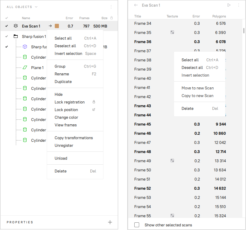
Figure 61 Workspace panel and respective context menus: object list on left and surface list on right.
Use the  button at the top right to select the columns to be displayed or to hide the panel.
Change the column order by drag-and-dropping their headers.
button at the top right to select the columns to be displayed or to hide the panel.
Change the column order by drag-and-dropping their headers.
Note
The column marked with appears automatically if you set the Lock registration or Lock position status for one or more objects using the context menu (see Operations with Objects for details on the context menu operations).
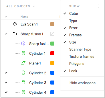
Figure 62 Selecting columns to be displayed.
Operations with Objects
In the Workspace panel, you can perform various types of operations with objects. All types of operations are available through the context menu called by clicking RMB on some object.
| Menu Item | Description |
|---|---|
| ALL OBJECTS filter | Instruct Workspace to display only particular types of the objects or all of them (see Figure 63). |
| Select all | Select (highlight) all objects for further operations on them. If only one or several objects of one group are selected in Workspace, the first run of this command will select all group objects, the second – all Workspace objects. |
| Deselect all | Reset any selection |
| Invert selection | Reset the current selection and select all other objects. |
| Group / Ungroup | You can group a few objects in the workspace according to some feature. Select required objects, call the context menu by clicking RMB and select Group. You will see that the objects are wrapped with a common header (for example, Group 1), which can be changed as well as the object names (see below). It is possible to create subgroups within groups. Resumed scans are also grouped automatically during scanning. Each scan imported from Leo will be included in a separate group inside the project group. See also Actions with Groups. |
| Rename | Select an object by clicking LMB on its name, hit F2 and specify a new object name in the opened dialog window. You can also rename many objects at once: select multiple objects (as described above) and then use F2 or RMB to rename them. |
| Duplicate | To make a complete duplicate of an object in the Workspace, right-click on the object and then select Duplicate.
A copy of the object will be created with the name like Copy of Fusion 1. |
| Show | Display the selected objects in the 3D View section. See Selecting Scans and Models for details. |
| Hide | Do not display an object in the 3D View section (cancel the Show operation). |
| Lock registration | Set the Locked registration status () to a scan, which blocks the reposition of the scan frames during Global Registration. See Locking Object’s Reposition for details. |
| Lock position | Set the Locked position status () to a scan, which blocks its reposition in some algorithms. See Locking Object’s Reposition for details. |
| Unlock | Remove the Locked registration and Locked position statuses from an object. |
| Change color | Call the color palette to change the color of an object or a group. See also Actions with Groups. |
| Copy transformations | Save the transformations of a scan and its frames for their further transfer to another scan. See Transferring Transformations for details. |
| Unregister | Reset the positions of individual frames in a scan computed during its registration. See Separating Scans for a use case. |
| Unload | Unload objects from RAM memory. See Memory Management: Object Unload for details. |
| Delete | Delete objects from your project. |
| Any column header | Sort the objects by either of their properties. Clicks: ascending order → descending → initial. |
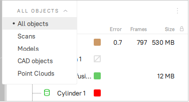
Figure 63 Filtering objects in Workspace.
Actions with Groups
In the Workspace panel you can perform the following actions with the groups of objects using the elements of the group header row:
| Action | How to perform |
|---|---|
| Select/Deselect | To select or deselect all objects in a group, click the group row in the column marked with . |
| Set/Change group color | By default, the group color is not set ( ). To set or change the color of a group, click the group row in the Color column area and select the desired color from the palette. When the group color is set and the group is collapsed in the Workspace panel, then all objects in the group are painted in the group color. Otherwise, each object is painted in its own color. ). To set or change the color of a group, click the group row in the Color column area and select the desired color from the palette. When the group color is set and the group is collapsed in the Workspace panel, then all objects in the group are painted in the group color. Otherwise, each object is painted in its own color. |
| Unset group color | To cancel the color setting for a group, right-click the group row in the Color column area. |
| Lock | To lock or unlock all objects in a group, click the group row in the Lock column area (). See Locking Object’s Reposition for details. |
Selecting Scans and Models
To view a scan or model in the 3D View window or to process it, you need to mark it with the icon in the Workspace panel. To navigate scans and models, use keys ↑ and ↓ or click an arbitrary area except those in , or color column ().
| Purpose | Method | Alternate Method |
|---|---|---|
| Highlight an object in Workspace to view its properties or run a command from the context menu | Left-click on the scan name | — |
| Toggle visibility and availability for processing (flag ) |
Left-click in the column |
|
| Batch selection (deselection) of objects for display and processing | Click in the rows of the required objects one by one |
|
| Select a single object for processing and deselect others | Select the object name using Ctrl+Alt+LMB | Use Ctrl+LMB in the empty area of the column |
In addition to the methods in the table above, you can use commands from the context menu by clicking RMB on the objects.
See also
The full list of hot keys in workspace.
Selecting Frames
Double-clicking the scan name (or using the View frames command in the context menu, or clicking the ![]() button near the scan name) opens the surface list, revealing all frames in that scan (see Figure 61, right).
button near the scan name) opens the surface list, revealing all frames in that scan (see Figure 61, right).
Highlighting specific frames will make them (and only them) appear in the 3D View window.
You can select frames in a number of ways:
- Click LMB on the frame name to select it while clearing other selections.
- Click LMB while holding the Ctrl key to select several frames at once.
- Click LMB while holding the Shift key to select a sequence of frames in the specified range.
- Click Ctrl+A/Ctrl+D to select/deselect all frames.
To start a sequential frame demonstration, use the  button at the upper right of the Surface list. To stop the demonstration, click
  .
.
Object Properties
At the bottom of the Workspace panel, you can see a Properties section. Click on it to expand it. Then select any object to display its properties. If no object is selected, the global settings of the project will be displayed in the Properties section.

Figure 64 Properties without a selected object.
Selecting a Point-Cloud Scan
Point-cloud scans contain only one surface. Click LMB on a point-cloud scan and look at the Properties section:
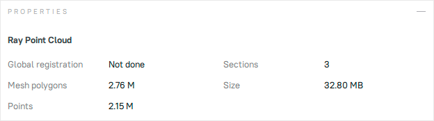
Figure 65 Properties of the point-cloud scan.
| Parameter | Description |
|---|---|
| Global registration | Shows whether the global registration procedure has been performed. |
| Mesh polygons | Since Artec Studio doesn’t display all the points constituting the scan, you can only see a mesh obtained from a simplified copy of the actual point cloud. |
| Points | Total number of points in the point cloud. |
| Sections | When you scan with Ray, you may select particular regions (sections) to narrow down the actual scene. This parameter stands for the number of these regions. |
| Size | The size (in MB) of the object in computer memory (not on a disk storage). |
Memory Management: Object Unload
When working with a large data set, you may often find it necessary to free up RAM without deleting any of the project data. To this end, Artec Studio implements a mechanism for selectively loading scans. You can move to disk any currently unused scans to free up extra RAM. If a particular algorithm later requires any of the unloaded scans, the application will automatically reload them.
To change the loading status, select the scans (models) in the Workspace window, click RMB and then select Unload in the pop-up menu.
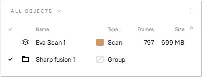
Figure 66 Unloaded scan.
Any scans (models) that are completely unloaded from memory will be displayed in a strikethrough font in the Workspace window and won’t appear in the 3D View window.
Algorithms may automatically change the loading status of project data in the following cases:
- You have selected unloaded scans for processing by clicking the flag. Artec Studio will load these scans into memory.
- Execution of the algorithm requires large amounts of memory. Artec Studio will unload unused scans, frames, textures or a combination thereof.
- Algorithm needs certain frames and it loads only them.
Note
In addition to 3D data, the change history can also consume a large portion of memory. For information on how to control the history size as well as how to unload or clear it, consult History of Project Changes.