3D Scanning at a Glance
Before you start using the guide, we want to show you how easy 3D scanning can be. This brief summary will help you understand the 3D scanning process with the Artec 3D tools and get started quickly. If you prefer to begin with comprehensive and detailed information, you can skip this chapter.
The figure below schematically shows a typical common sequence of the 3D scanning and processing in the Artec 3D environment.

- Scanning
- Working with a scanner, transferring data from the scanner to a PC (mobile device) for further processing.
- Cleaning
- Rough cleaning of scans with the Eraser tool. Removal of the base surface and side objects.
- Alignment
- Aligning multiple scans of the same object.
- Registration
- Optimizing the position of frames within one or more scans.
- Fusion
- Creating a mesh model on the base of scans.
- Postprocessing
- Mesh simplification, smoothing and other optional steps.
Note
The need for a particular step depends on the individual case.
Preparation
PC Requirements
Besides a scanner itself, you need a PC to create and process models in Artec Studio. Your PC must run on the 64-bit version of Microsoft Windows 7, 8 or 10. The more powerful the PC, the better. The main memory (RAM) and graphics card are the most critical components (visit our FAQ page for more information).
Activation
Warning
Don’t connect the scanner just yet! Continue reading for more information.
- Register for an account at my.artec3d.
- Sign in and download Artec Installation Center from the welcome page.
- Install Artec Installation Center. When prompted, enter your email and password.
- Plug the scanner into a power outlet, then connect it to your PC using the USB cable.
- Wait for Windows to detect the scanner. Click Activate.
- Click Install in the Software section to get Artec Studio running on your machine.
(For more details, see User Account, Scanner Activation and Offline Activation.)
Prepare Object and Scene (Common Recommendations)
Most objects are easily scanned, but observe the following recommendations for best results:
Before scanning transparent, reflective or black objects, we suggest applying a powder coating or a special anti-glare spray.
To scan monochrome objects with simple geometric shapes, do the following:
- Add auxiliary objects (e.g., crumpled paper) to the scene
- Paint markers (e.g., “X” shapes) on the surrounding surfaces
Be sure to provide good ambient light.
A detailed information on preparing for different scanner types is available at the following links:
Scanning
Launch Artec Studio, then aim the scanner at the object.
Press
 on the scanner to start Preview mode. If your scanner lacks this button, first open the Scan panel.
- Geometry + Texture is the default scanning mode and is suitable for most cases
- For older PCs, Geometry mode is a good alternative
- The Real-time fusion mode creates a model in real time, allowing you to skip postprocessing; click Stop, then select the Real-time fusion checkbox and click Preview.
Make sure the object is visible, then press
once again to initiate recording. If possible, scan all sides of the object in one go, slowly moving the scanner around it as pictured below.Note
While scanning, pay closer attention to the object on the screen than to the actual object.
If you hear an alert sound and the screen displays an error against a red background, smoothly aim the scanner at the area you just captured. Possible reasons for the “Tracking lost” error include the following:
- You are scanning simple geometric shapes
- The part of the object you are scanning is too small
- Scanner movement is too fast
Press
 to display the scan in Artec Studio.
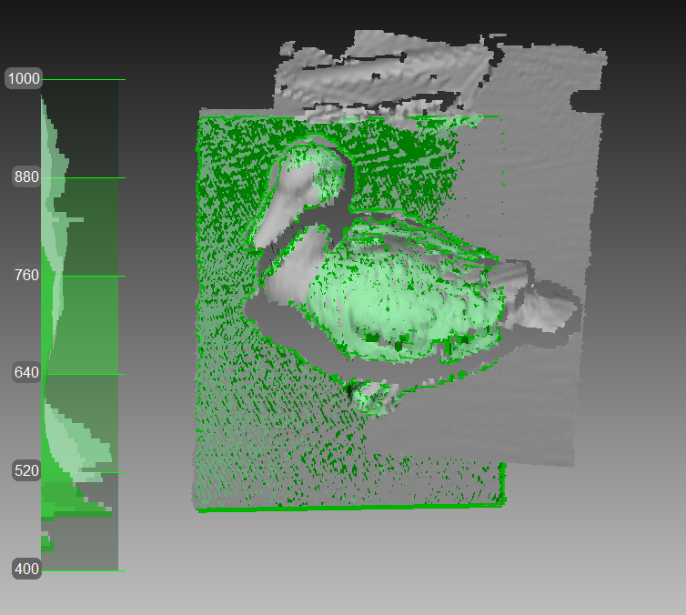
Figure 1 Scanning with Eva.
Turn and Scan (Optional)
Turn the object and capture any remaining unscanned regions (press ). Also, to facilitate alignment, record at least one previously scanned region.
- Launch Artec Studio, connect the scanner to your PC and turn it on. Calibrate it if necessary.
- Fit an object in the camera view. The object must be entirely visible. For large objects, consider removing extra spacers from the scanner.
- Adjust Brightness and other settings as necessary. Tune it to minimize areas highlighted in red (potentially noisy areas).
- Select Scanning path. For simple cases, use the Preview mode.
- Click Scan. Micro will start capturing frame while swinging the L-shaped arm and rotating the turntable.
If necessary, flip the object and affix it. Then repeat the steps above to scan the remaining areas. You’ll need to later align the scans obtained this way.
Figure 2 Aligned scans from Micro.
See also
Scanning with Micro in details.
Since Artec Leo is a self-inclusive device featuring computing and graphics processing units, you don’t need to connect it to a PC running Artec Studio while scanning.
- Tap New project or press the red button on the handle of the scanner. Leo will start preview, i.e. building surfaces without recording them.
- Configure the Leo settings as you need.
- Direct the scanner at the object. Practice your movements and assess the quality of the surface being reconstructed on the screen.
- Once you’re ready, tap
 or press the red button on the handle of the scanner.
 - Scan the object from all possible sides.
- Tap
 or press the red button on the handle of the scanner.
 - Rotate or turn the object upside down to scan the missing regions.
- Tap Close if you are done with the scan.
Once you have recorded a scan, it is added to the project.
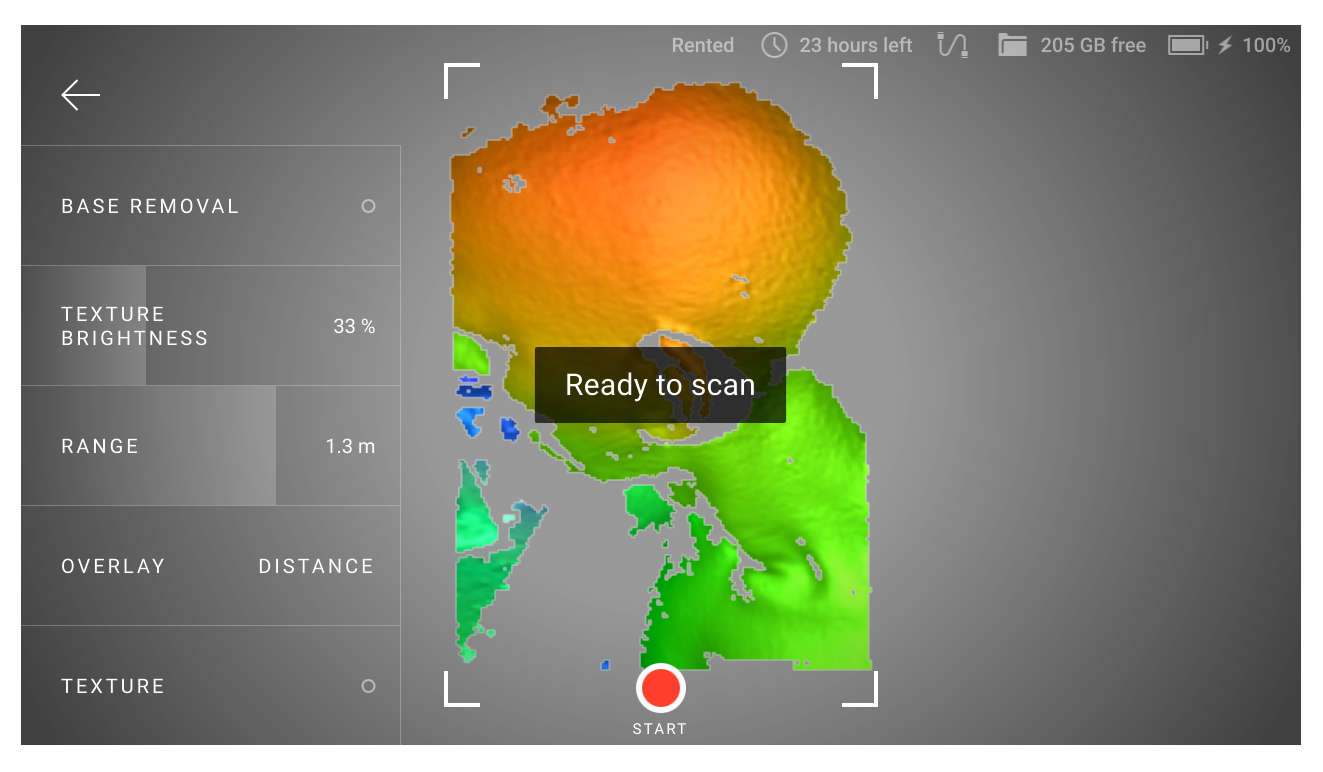
Figure 3 Scan screen.
It is possible to import projects from Artec Leo either over a network from Artec Studio or using a microSD card. See here for details.
See also
Scanning with Leo in details.
Note
Ray can work both through Artec Studio and the mobile application Artec Remote. This short introductory document will cover the work with Artec Studio.
First, you should make a preview scan for the following reasons: to get a low-resolution image of the area you are scanning so you can see the desired object; to estimate the required point density for scanning.
- Ensure Ray is connected to your computer.
- Launch Artec Studio.
- Open the Scan panel. Click Scan with Ray. The application will open the Ray scan panel.
- Click Preview. Ray will capture a preview.
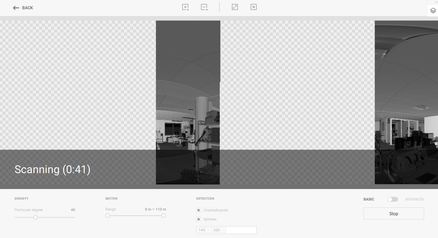
Figure 4 Ray preview scanning.
Once you have a preview, you can
- Select the entire preview image to scan the whole space.
- Locate and mark sections to scan particular objects in the scene using interface buttons like
 and
and 
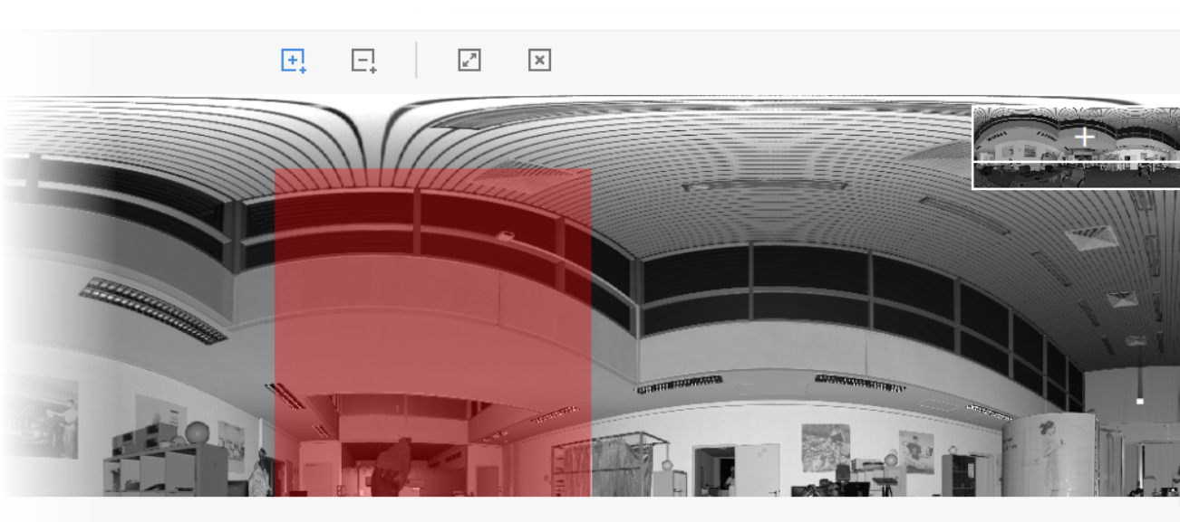
Figure 5 Marking section.
Adjust point density and other necessary settings.
Scan selected sections using the Scan in Artec Studio.
Use Autopilot
For beginners, the easiest way to obtain a 3D model is by using Autopilot. It’s also a great time saver for advanced users. If you prefer performing all the steps manually, refer to the Process Manually section.
Autopilot is a special mode that helps users obtain a complete 3D model without learning all the ins and outs of postprocessing. It consists of two major parts: semiautomatic (editing and alignment) and automatic.
To produce a model,
Click Autopilot in the left panel or hit F9.
Become familiar with the steps that you will perform in this guided mode (listed in the welcome screen).
In the Workspace panel, use the
 flag to mark all scans that you intend to use, then click Next.
Then specify the input parameters for the model-creation step and click Next. Primary settings may include the following:
Note
We suggest consulting the tool tips, which you can reveal by clicking the
 button next to the option name.
- Scan quality (geometry). Click to determine whether your scan of the object has the correct geometry by examining the tool-tip images.
- Scan quality (texture). Click , look at the images and decide whether your scan has sufficient texture.
- Hard-to-scan surfaces. Select the checkbox if your object has surfaces that are difficult to capture. Consult the image samples by clicking the button.
- Decide on the Object size by referring to the image samples.
- Leave the default values for the remaining options in this window (sufficient for most cases). For advanced scenarios, you can tweak these settings (more details appear in the sidebar).
- Scan quality (geometry). Click
If necessary, erase any extraneous objects that can hinder processing and postprocessing. Learn how to use Eraser by consulting the Erasing Portions of Scans (Eraser) section.
Once you’re done, click Next. If the object was captured over several scans, Autopilot will align them and show you the result. You can approve it or align the scans manually (consult Manual Rigid Alignment Without Specifying Points).
Click Next.
Autopilot will begin processing and then postprocessing. Once it’s finished, a message will appear informing you that the model is ready. Click OK.
The automatic steps can be grouped as follows:
Processing
- Global registration
- Outlier removal
- Fusion
Postprocessing
- Small-object filter
- Mesh simplification
- Texturing
Process Manually
Crop Surroundings
Once you finish, click File and select Save project. Close the Scan panel. You can now crop the surroundings.
Purpose: To erase auxiliary surfaces (e.g., a table or floor).
Steps: Open Editor → Eraser → Cutoff-plane selection. Follow the panel instructions.
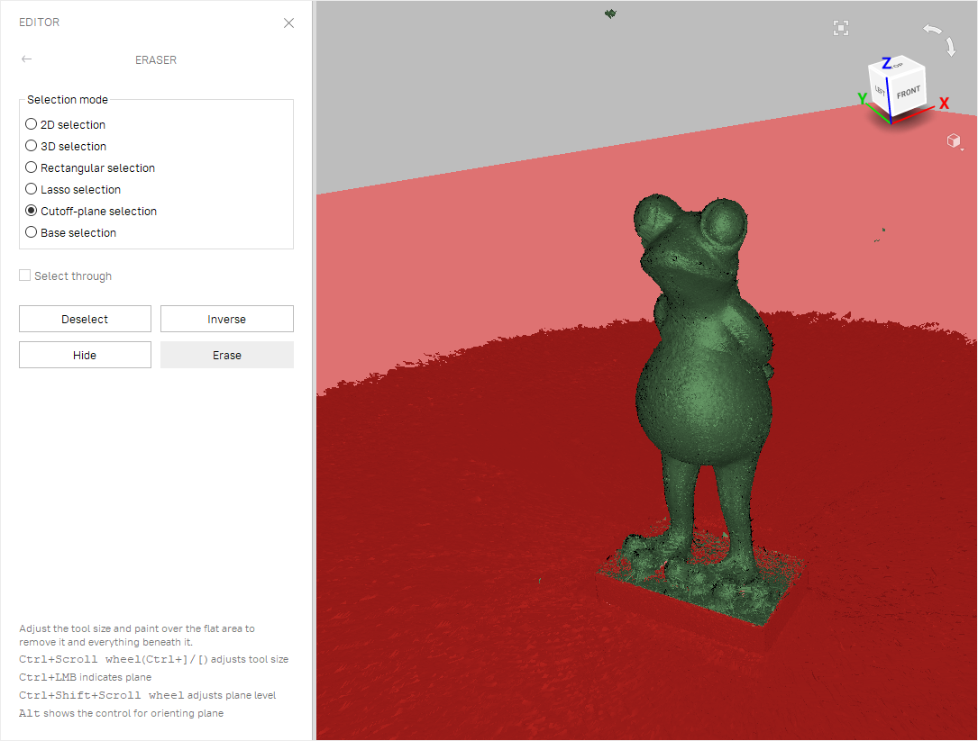
Tip
Use freely other types of the Eraser (not only Cutoff-plane selection) to remove other unwanted elements from the scan.
See also
Align
Tip
If you have only one scan (see the Workspace panel), or if you used Auto-alignment during scanning, you can skip this step.
Purpose: To align several scans.
Steps:
- Mark two or more scans using , click Align and select those scans in the Rigid tab while holding the Ctrl key.
- Click Auto-alignment.
- If alignment fails owing to a lack of texture or lack of overlapping areas, manually match the features among the scans and click the Align button.
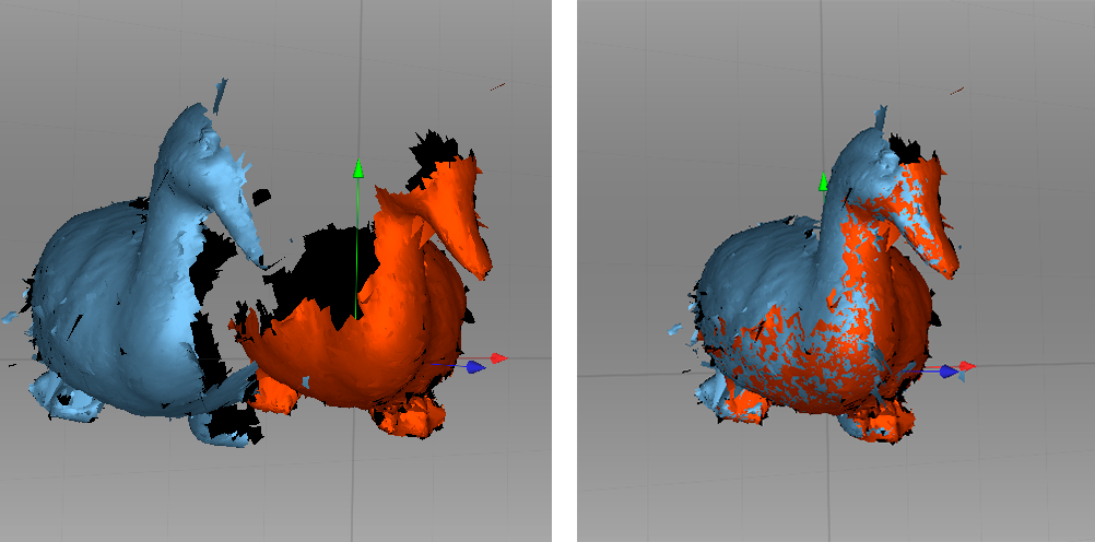
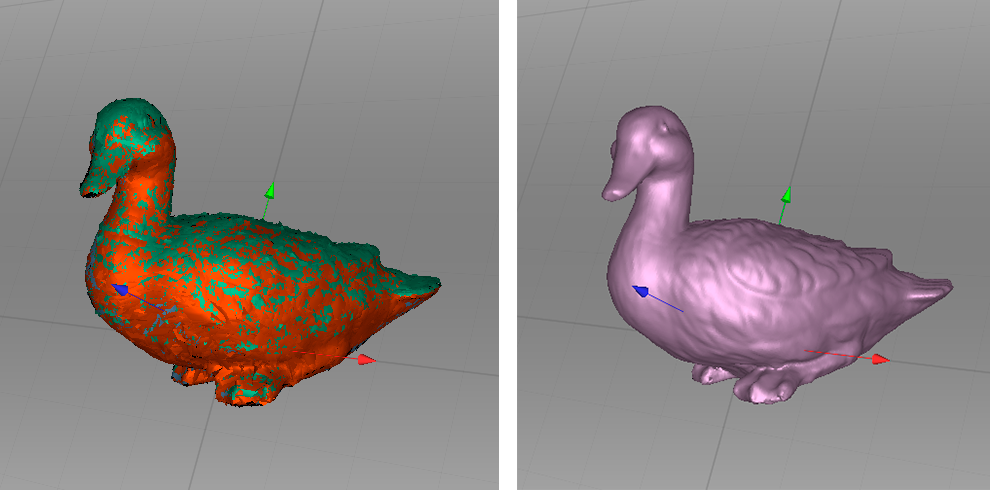
Figure 12 Two scans before and after alignment.
See also
Alignment in details.
Global Registration
Purpose: To simultaneously optimize the frame position across all scans, thus preparing them for further processing.
Steps: Mark scans using , then click Tools → Global registration → Apply.
Tip
If you see some obvious problems with preliminary (Rough) registration after scanning, try to resolve them by Global registration of each scan separately.
See also
Global Registration in details.
Eliminate Noise
Purpose: To erase large outliers and some noise.
Steps: Open Tools → Outlier removal → Apply.
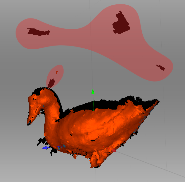
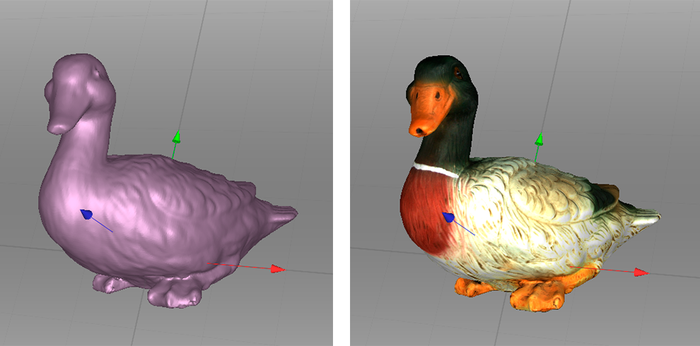
Figure 13 Outlier removal.
See also
Editing Scans and Eliminating 3D Noise (Outlier Removal) for more details.
Fusion
Purpose: To create a model (a single surface, as opposed to the multiple surfaces that constitute the source scan).
Steps: Select Tools → Smooth fusion → Fill holes → All (watertight) → Apply.
Tip
To obtain sharper surfaces, select Sharp fusion.
In any case, 3D resolution can be adjusted: the smaller the value, the more precise the resulting surface.
See also
Creating Models (Fusion) in details.
Erase Flaws (Optional)
Purpose: To erase any outliers and poorly scanned regions.
Steps: Click Editor → Defeature brush. Follow the instructions.
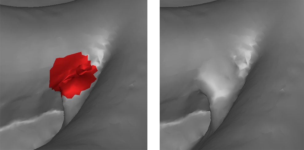
Figure 15 Using Defeature brush.
See also
Simplify Mesh
Purpose: To reduce the file size by decreasing the number of polygons without significantly distorting the actual 3D geometry.
Steps: Click Tools → Mesh simplification → Apply.
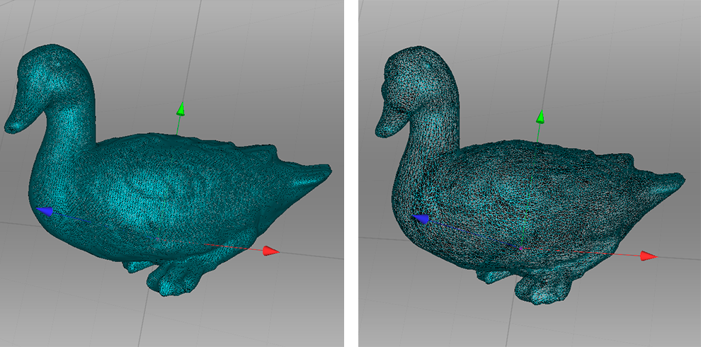
Figure 16 Mesh simplification.
See also
Mesh Simplification in details.
Tips and Tricks
- You can reset all settings to their defaults using F10 → Scan tab → Reset to defaults.
- To return any altered parameters in the Tools panel to their default values, click the adjacent
 button. A parameter lacking this button is set to the default value.
 - Save screenshots by hitting Ctrl+Shift+S.
- Apply annotations using Measures: click Ctrl+LMB to tag a label and type text, then click
 or anywhere outside the label’s pop-up window.