Scanning
This chapter covers everything you need to know to scan using Artec Ray.
See also
Preview Scan
You should make a preview scan for the following reasons:
To get a low-resolution image of the area you are scanning so you can see the desired object.
To estimate the required point density for scanning.
To ensure that the newly set Ray scans correctly.
If you need a full scan and you understand how the parameters work, you can skip the preview (see Scanning Configuration).
To make a preview scan, follow these steps:
Ensure Artec Ray was turned on with the USB cable connected to your computer.
Launch Artec Studio.
Open the Scan panel. Click Scan with Ray. The application will open the Ray scan panel.
Click Preview. Ray will capture a preview.
Once the preview of unwrapped 3D data is ready, you can examine particular regions. Use the Scroll wheel with the cursor on the image.
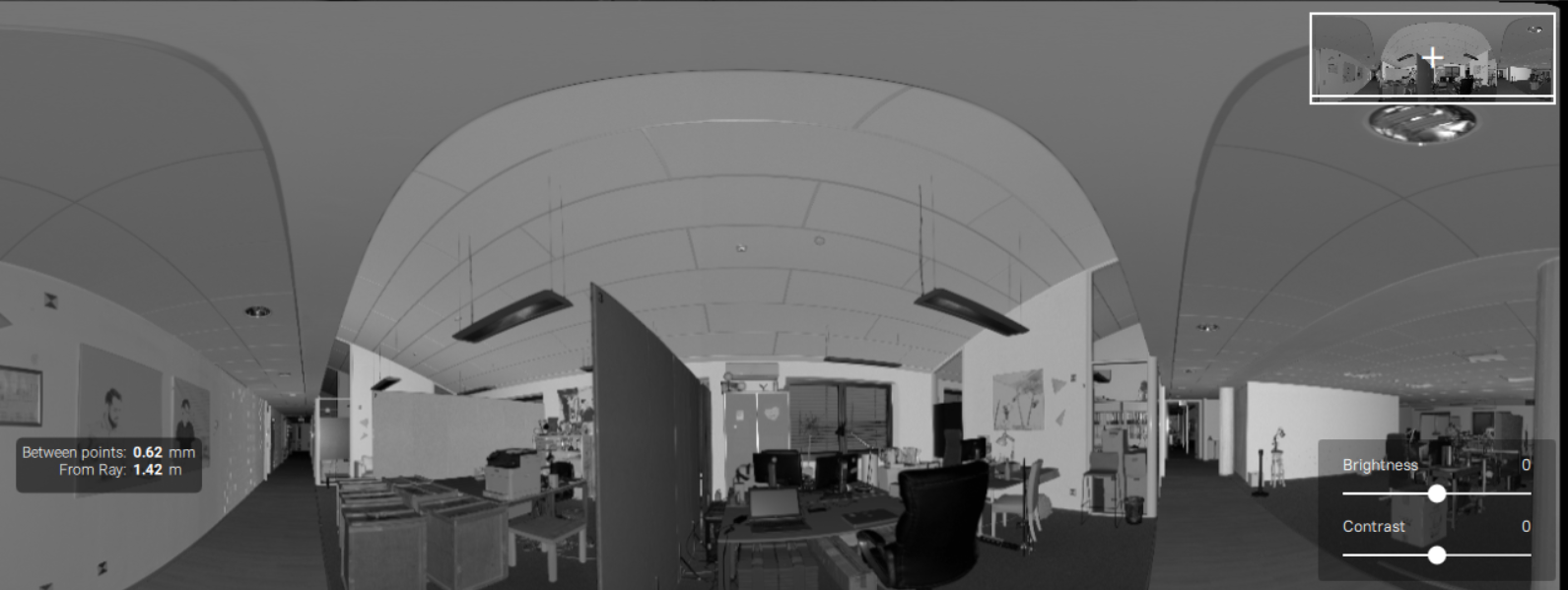
The objects located more than 30 meters from the scanner may be barely visible in the preview. To improve their visibility, use the Brightness and Contrast sliders in the lower-right conner of the 3D window (see the image below).
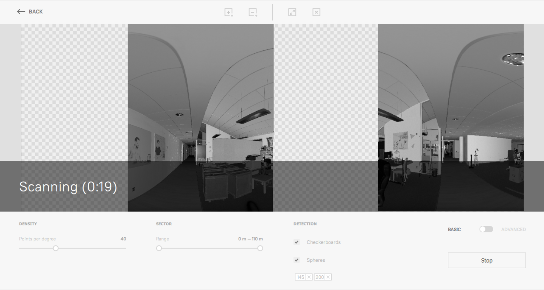
Figure 10 Creating the preview scan.
To preview a scene before scanning, follow these steps:
Ensure Ray was turned on, with the USB cable unplugged.
Open the Artec Remote app in your phone or device; and connect to Ray via Wi-Fi.
Tap the Preview button. Artec Ray will start making a preview.
The window will split into two panels and each of them will start filling with the scanned data.
When the preview is complete, the captured data (low-resolution) appears in the main window.
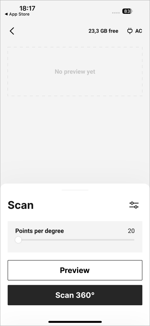
Figure 11 Preview scan in iOS for a Artec Ray scan.
To preview a scene before scanning, follow these steps:
Ensure Ray was turned on, with the USB cable unplugged.
Open the Artec Remote app in your phone or device, and connect to Ray via Wi-Fi.
Tap the Preview button. Artec Ray will start making a preview.
The window will split into two panels and each of them will start filling with the scanned data.
When the preview is complete, the captured data (low-resolution) appears in the main window.
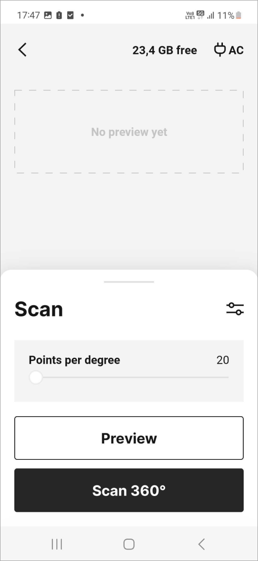
Figure 12 Preview scan in Android for a Artec Ray scan.
Area Selection
Once you have a preview, you can
Select particular objects or areas of the scene using rectangular selection.
Use the following buttons to control selections:
|
Select (add) a rectangular section |
|
Clear all selected sections |

Example: Marking Rectangular Selection
Click the
 button.
Place the cursor at any corner of the area you want to scan in detail. Left click once.
Move the cursor to an opposite corner of the area you want to scan and again left click to select the area.
If you want to define additional areas to scan, repeat the previous steps.
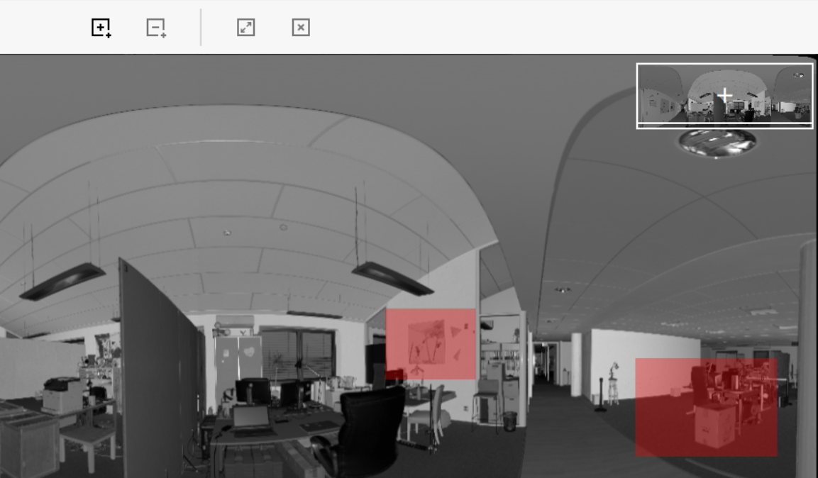
Figure 13 Sections marked in the preview image.
Use the following buttons to control selections:
|
Select (add) a rectangular section |
|
Clear all selected sections |
Marking Custom Selection
To start selecting sections, tap the Select area  button. Tap and hold to start drawing your custom selection region. Drag the selection to cover the area needed. To save the selection, release the finger off the screen.

Figure 14 Marking the custom selection.
Deleting Custom Selection
To mark the deleting custom selection, tap the  button. Tap and hold to start drawing your deleting region. Drag the selection to cover the deleted area. To delete the selection, release the finger off the screen.
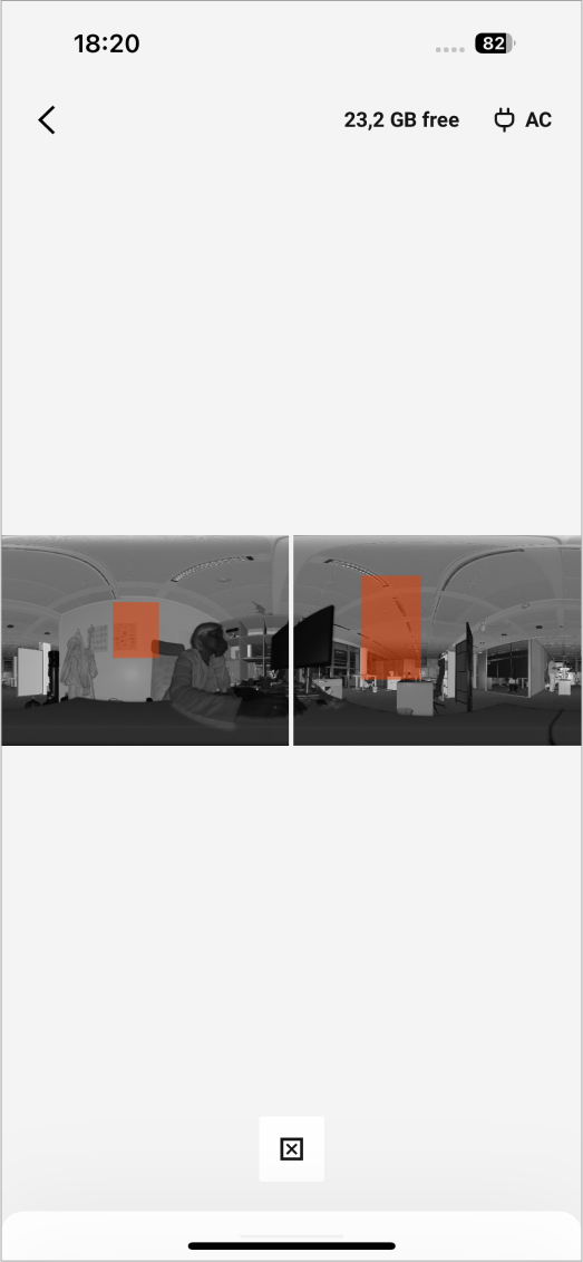
Figure 15 Deleting the custom selection.
Use the following buttons to control selections:
|
Select (add) a rectangular section |
|
Clear all selected sections |
Marking Custom Selection
To start selecting sections, tap the Select area button. Tap and hold to start drawing your selection region. Drag the selection to cover the area needed. To save the selection, release the finger off the screen.
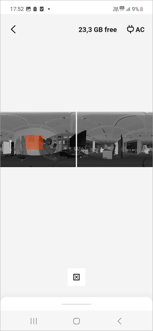
Figure 16 Marking the rectangular selection.
Scanning Configuration
Before you start scanning, you can specify a set of parameters.
Adjust Point Density
Scan resolution is measured at points per degree and varies with distance to objects. The larger the value, the better the resolution and the longer the scanning time will be. Estimate and adjust point density on different distances to ensure the required scanning quality for a particular surface.
In the 3D window, use the mouse cursor to identify the distance Between points at a particular distance From Ray in a given preview area (see Preview Scan).
Decide whether the value is sufficient.
Increase the density level by the Points per degree slider if you need a better resolution for distant objects.
Estimate the Distance between points once again.
In advanced mode (see here), the point-density slider becomes two independent sliders:
Horizontal density per degree |
20–80 |
Lines per degree |
Vertical density per degree |
20–80 |
Points per degree |
Create a preview scan.
Decide whether the quality of the scan is sufficient.
Increase the density level by the Points per degree slider if you need a better resolution for particular distant objects.
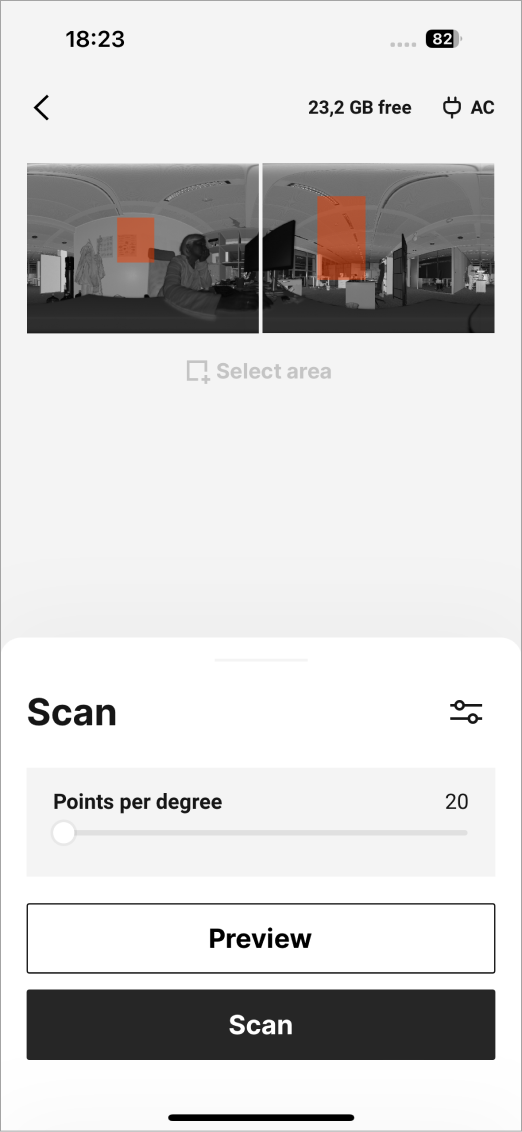
Figure 17 The basic scanning resolution settings.
In basic mode, available scan resolution range is 20–80 (in points per degree). In advanced mode (see here), the point-density slider becomes two independent sliders:
Horizontal density per degree |
20–80 |
Lines per degree |
Vertical density per degree |
20–80 |
Points per degree |
Create a preview scan.
Decide whether the quality of the scan is sufficient.
Increase the density level by the Points per degree slider if you need a better resolution for particular distant objects.
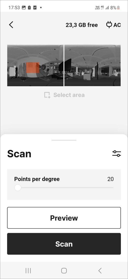
Figure 18 The basic scanning resolution settings.
In basic mode, available scan resolution range is 20–80 (in points per degree). In advanced mode (see here), the point-density slider becomes two independent sliders:
Horizontal density per degree |
20–80 |
Lines per degree |
Vertical density per degree |
20–80 |
Points per degree |
Tweak Settings
There are two modes of scanning settings:
Basic mode is used by default.
Advanced mode is for more detailed adjustment (use the eponymous toggle to activate).
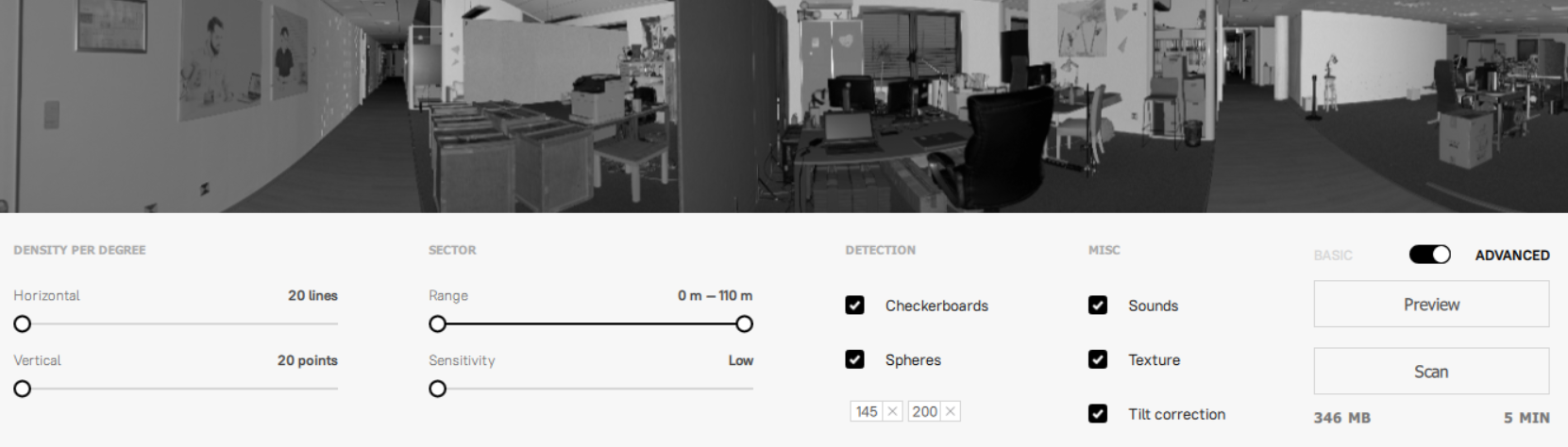
Figure 19 The Advanced mode settings.
The table below summarizes the available parameters.
Parameter |
Value range |
Description |
Basic |
Advanced |
|---|---|---|---|---|
Range |
0–110m |
Working distance within which the objects you want to scan are situated. Use the two-sided slider to adjust this range. Specifying an excessively large range may increase the scanning time and output-file size. |
✓ |
✓ |
Density (per degree) |
20-80 lines/points per degree |
See Adjust Point Density. The larger the value, the better the resolution and the longer the scanning time. In the basic mode, the horizontal and vertical densities are distributed proportionally. |
✓ |
✓ |
Sensitivity |
Low, Medium, High |
|
✓ |
|
Spheres |
|
Toggle detection of the target spheres and specify their diameters using the semicolon delimiter. Always clear unused values. |
✓ |
✓ |
Checkerboards |
On/Off |
Toggle detection of the checkerboard targets. |
✓ |
✓ |
Texture |
On/Off |
Specify whether to record the texture. |
✓ |
|
Tilt correction |
On/Off |
Enable compensation for incorrect Ray leveling, between 0 and 15°. |
✓ |
|
Sounds |
On/Off |
Toggle audio notifications during scan. This indicator may be helpful to monitor the scan’s progress without having to watch the application’s window. |
✓ |
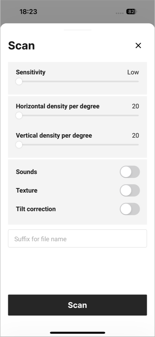
Figure 20 The Advanced mode settings.
The table below summarizes the available parameters.
Parameter |
Value range |
Description |
Basic |
Advanced |
|---|---|---|---|---|
Sensitivity |
Low, Normal, High |
|
✓ |
|
Density per degree |
20-80 lines/points per degree |
See Adjust Point Density. The larger the value, the better the resolution and the longer the scanning time. In the basic mode, the horizontal and vertical densities are distributed proportionally. |
✓ |
✓ |
Sounds |
|
Toggles the audio notifications during scanning. This indicator may be helpful to monitor the scan’s progress without having to watch the Artec Remote app’s screen. |
✓ |
|
Texture |
|
Toggles whether to record the texture. |
✓ |
|
Tilt correction |
On/Off |
Enable compensation for incorrect Ray leveling, between 0 and 15°. |
✓ |
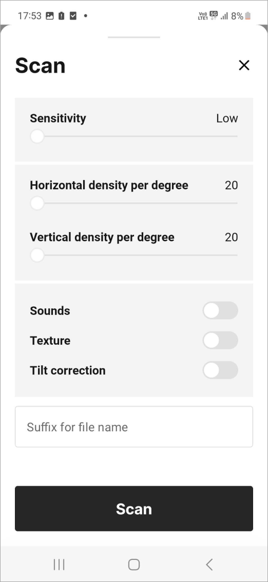
Figure 21 The Advanced mode settings.
The table below summarizes the available parameters.
Parameter |
Value range |
Description |
Basic |
Advanced |
|---|---|---|---|---|
Sensitivity |
Low, Normal, High |
|
✓ |
|
Density per degree |
20-80 lines/points per degree |
See Adjust Point Density. The larger the value, the better the resolution and the longer the scanning time. In the basic mode, the horizontal and vertical densities are distributed proportionally. |
✓ |
✓ |
Sounds |
|
Toggles the audio notifications during scanning. This indicator may be helpful to monitor the scan’s progress without having to watch the Artec Remote app’s screen. |
✓ |
|
Texture |
|
Toggles whether to record the texture. |
✓ |
|
Tilt correction |
On/Off |
Enable compensation for incorrect Ray leveling, between 0 and 15°. |
✓ |
Scanning
Ray has following scan modes:
Full scan—if you need to scan the whole area without preview
Particular scan—if you have marked the selected regions in a preview image (impossible in Autonomous mode)
Specify the range (see the table above).
Adjust the point density using the Points per degree slider (see Adjust Point Density) and other parameters (Tweak Settings) as necessary. You may need to turn on Advanced mode to access some of these parameters.
Click Scan. The 3D View window will split into two panels, and each will start displaying the scanned data. Artec Studio will also display estimated scanning time.
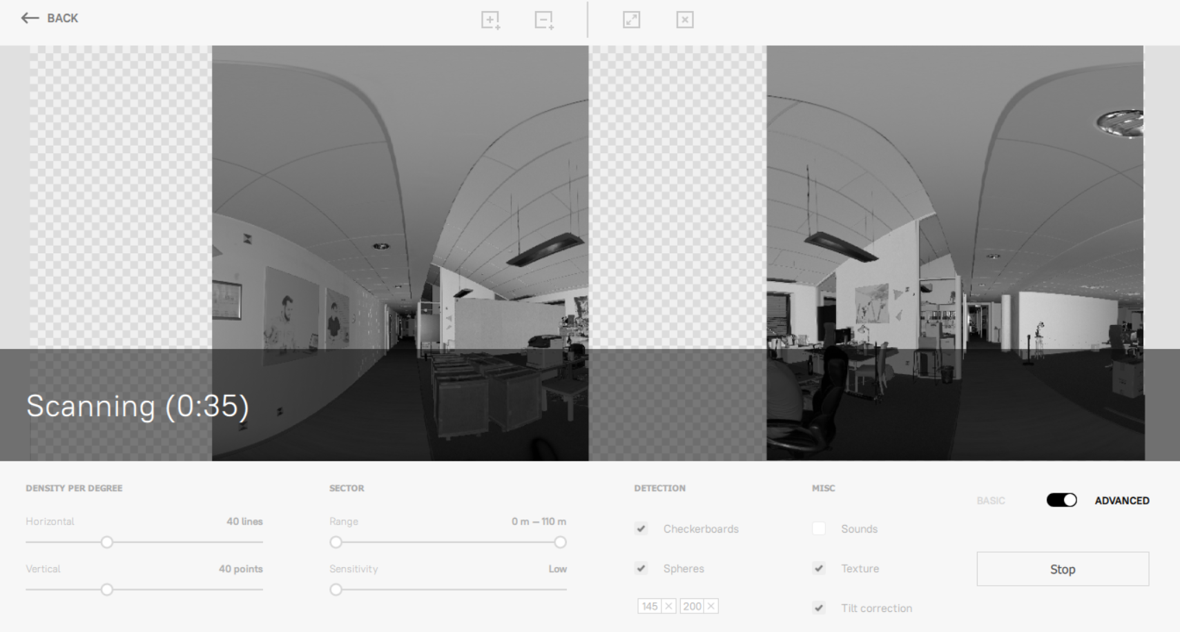
Figure 22 Scanning process.
To cancel the scanning, click the Stop button.
Note
Full scan is a default mode. It performs by the Scan 360° button. If you make a preview and mark selections, this button is changed to Scan and performs a particular scan.
Adjust the point density using the Points per degree slider (see Adjust Point Density) and other parameters (Tweak Settings) as necessary. You may need to turn on Advanced mode to access some of these parameters.
To start scanning, tap the Scan 360° or Scan button.
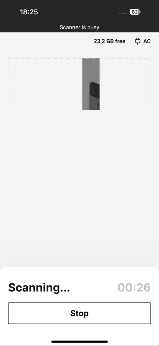
Figure 23 Scanning in progress.
You can control Artec Ray battery level and SD-card free space using the icons at the upper right of the application screen:
|
Artec Ray SD-card unused space size (GB) |
|
Current battery level |


To cancel the scanning, tap the Stop button.
Adjust the point density using the Points per degree slider (see Adjust Point Density) and other parameters (Tweak Settings) as necessary. You may need to turn on Advanced mode to access some of these parameters.
To start scanning, tap the Scan button.
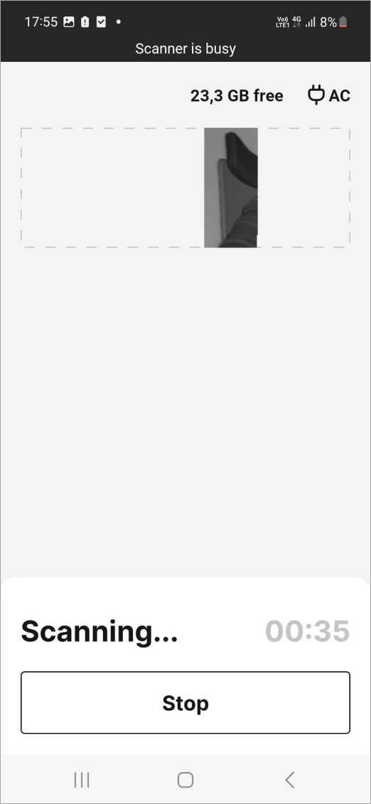
Figure 24 Scanning in progress.
To cancel the scanning, tap the Stop button.
To avoid unexpected interruptions of the scanner operation, control the Artec Ray battery level and SD-card free space while scanning with the icons at the upper right of the Settings screen:
|
Artec Ray SD-card unused space size (GB) |
|
Current battery level |


If you are scanning a relatively simple space without many arrangements or viewpoints, you can operate the scanner using its green top LED button and on-board memory.

Figure 25 Button to start and stop autonomous scanning.
Make sure Ray was turned on with the USB cable unplugged.
Press the green top LED button to start scan.
When the scanner stops rotating and the LED ring returns to solid green, move to the next scan position (if applicable) and press the button again to begin your next scan.
If you press this button before step No. 3 of the procedure above, Ray stops scanning.
Change Viewpoint
In some cases—for example, when scanning an object in the middle of the room—you may need to add scans from other viewpoints. Once you have defined the required positions, follow these steps:
Move Ray to the next position.
Ensure the scanner rests firmly on the floor.
Capture a preview and configure the settings.
Scan an area or object.
Repeat the steps above for the remaining viewpoints.